HP PageWide XL 5000 User Guide - Page 124
Small color differences between adjacent CIS modules, differences
 |
View all HP PageWide XL 5000 manuals
Add to My Manuals
Save this manual to your list of manuals |
Page 124 highlights
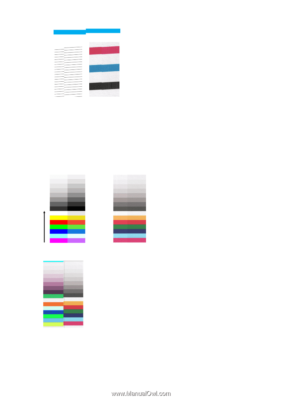
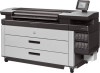
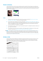
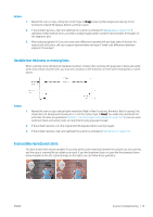
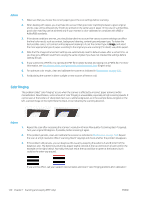
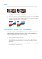
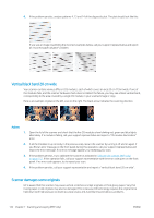
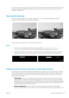
The four vertical thin black lines at the beginning and the end of the diagnostic plot show, approximately, the position of the intersection between CIS modules, where this kind of error usually appears. If the error appears outside these areas, call your support representative and report "line discontinuities within a CIS module". Small color differences between adjacent CIS modules When scanning wide plots, sometimes slightly different colors can be seen at both sides of the junction between two CIS modules. This issue, if present, can be easily seen by analyzing patterns 9 of the diagnostic plot at the intersection between CIS modules. Here are some examples. Note the black arrow indicating the scanning direction in these examples. Sometimes the color mismatch between adjacent modules can be enormous, showing a serious scanner malfunction, as in the following example. 118 Chapter 7 Scanning and copying (MFP only) ENWW
-
 1
1 -
2
-
3
-
4
-
5
-
6
-
7
-
8
-
9
-
10
-
11
-
12
-
13
-
14
-
15
-
16
-
17
-
18
-
19
-
20
-
21
-
22
-
23
-
24
-
25
-
26
-
27
-
28
-
29
-
30
-
31
-
32
-
33
-
34
-
35
-
36
-
37
-
38
-
39
-
40
-
41
-
42
-
43
-
44
-
45
-
46
-
47
-
48
-
49
-
50
-
51
-
52
-
53
-
54
-
55
-
56
-
57
-
58
-
59
-
60
-
61
-
62
-
63
-
64
-
65
-
66
-
67
-
68
-
69
-
70
-
71
-
72
-
73
-
74
-
75
-
76
-
77
-
78
-
79
-
80
-
81
-
82
-
83
-
84
-
85
-
86
-
87
-
88
-
89
-
90
-
91
-
92
-
93
-
94
-
95
-
96
-
97
-
98
-
99
-
100
-
101
-
102
-
103
-
104
-
105
-
106
-
107
-
108
-
109
-
110
-
111
-
112
-
113
-
114
-
115
-
116
-
117
-
118
-
 119
119 -
 120
120 -
 121
121 -
 122
122 -
 123
123 -
 124
124 -
 125
125 -
 126
126 -
 127
127 -
 128
128 -
 129
129 -
130
-
131
-
132
-
133
-
134
-
135
-
136
-
137
-
138
-
139
-
140
-
141
-
142
-
143
-
144
-
145
-
146
-
147
-
148
-
149
-
150
-
151
-
152
-
153
-
154
-
155
-
156
-
157
-
158
-
159
-
160
-
161
-
162
-
163
-
164
-
165
-
166
-
167
-
168
-
169
-
170
-
171
-
172
-
173
-
174
-
175
-
176
-
177
-
178
-
179
-
180
-
181
-
182
-
183
-
184
-
185
-
186
-
187
-
188
-
189
 |
 |