HP PageWide XL 5000 User Guide - Page 128
Vertical black band 20 cm wide, Scanner damages some originals, If this operation fails
 |
View all HP PageWide XL 5000 manuals
Add to My Manuals
Save this manual to your list of manuals |
Page 128 highlights
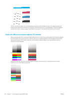
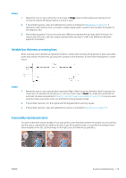
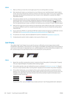
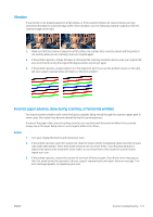
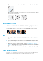
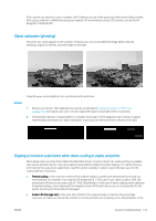
4. If the problem persists, analyze patterns 4, 13 and 14 of the diagnostic plot. The plot should look like this: If you see an image resembling the incorrect examples below, call your support representative and report an "incorrect paper advance" problem. Vertical black band 20 cm wide Your scanner contains various different CIS modules, each of which covers an area 20 cm (7.9 in) wide. If one of the modules fails, and the scanner hardware check does not detect the failure, you may see a black vertical band, corresponding to the area covered by a single CIS module, in your scanned image or copy. Here is an example: original on the left, scan on the right. The black arrow indicates the scanning direction. Actions 1. Open the lid of the scanner and check that the five CIS modules show blinking red, green and blue lights alternately. If a module is failing, call your support representative and report a "CIS module illumination" error. 2. If all the modules lit up correctly in the previous step, restart the scanner by turning it off and on again. If you find an error message on the front panel during this operation, call your support representative and report the error message. If no error message appears, try repeating your scan. 3. If the problem persists, try to calibrate the scanner as indicated in Calibrate the scanner (MFP only) on page 157. If this operation fails, call your support representative with the error code given on the front panel. If no error code appears, try to repeat your scan. 4. If the problem persists, call your support representative and report a "vertical black band 20 cm wide". Scanner damages some originals HP is aware that this scanner may cause vertical scratches on inkjet originals on thick glossy paper. Very thin tracing paper or old originals may also be damaged. This is because CIS technology requires the original to be held down with high pressure to obtain accurate results and avoid blurring and defocus problems. 122 Chapter 7 Scanning and copying (MFP only) ENWW
-
 1
1 -
2
-
3
-
4
-
5
-
6
-
7
-
8
-
9
-
10
-
11
-
12
-
13
-
14
-
15
-
16
-
17
-
18
-
19
-
20
-
21
-
22
-
23
-
24
-
25
-
26
-
27
-
28
-
29
-
30
-
31
-
32
-
33
-
34
-
35
-
36
-
37
-
38
-
39
-
40
-
41
-
42
-
43
-
44
-
45
-
46
-
47
-
48
-
49
-
50
-
51
-
52
-
53
-
54
-
55
-
56
-
57
-
58
-
59
-
60
-
61
-
62
-
63
-
64
-
65
-
66
-
67
-
68
-
69
-
70
-
71
-
72
-
73
-
74
-
75
-
76
-
77
-
78
-
79
-
80
-
81
-
82
-
83
-
84
-
85
-
86
-
87
-
88
-
89
-
90
-
91
-
92
-
93
-
94
-
95
-
96
-
97
-
98
-
99
-
100
-
101
-
102
-
103
-
104
-
105
-
106
-
107
-
108
-
109
-
110
-
111
-
112
-
113
-
114
-
115
-
116
-
117
-
118
-
119
-
120
-
121
-
122
-
 123
123 -
 124
124 -
 125
125 -
 126
126 -
 127
127 -
 128
128 -
 129
129 -
 130
130 -
 131
131 -
 132
132 -
 133
133 -
134
-
135
-
136
-
137
-
138
-
139
-
140
-
141
-
142
-
143
-
144
-
145
-
146
-
147
-
148
-
149
-
150
-
151
-
152
-
153
-
154
-
155
-
156
-
157
-
158
-
159
-
160
-
161
-
162
-
163
-
164
-
165
-
166
-
167
-
168
-
169
-
170
-
171
-
172
-
173
-
174
-
175
-
176
-
177
-
178
-
179
-
180
-
181
-
182
-
183
-
184
-
185
-
186
-
187
-
188
-
189
 |
 |
