Panasonic HPX500 Operating Instructions - Page 131
Connecting to External Devices, Connecting to External Devices Using USB2.0 Port (PC mode
 |
UPC - 791871302965
View all Panasonic HPX500 manuals
Add to My Manuals
Save this manual to your list of manuals |
Page 131 highlights
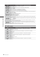
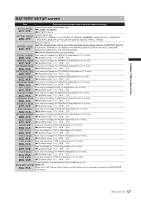
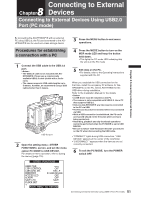
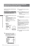
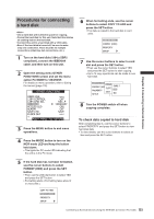
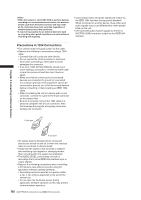
Connecting to External 8 Chapter Devices Connecting to External Devices Using USB2.0 Port (PC mode) Chapter 8 Connecting to External Devices By connecting the AG-HPX500P/E with an external PC using USB 2.0, the P2 card connected to the AGHPX500P/E can be used as a mass storage device. 3 Press the MENU button to end menu operations. Procedures for establishing a connection with a PC 1 Connect the USB cable to the USB 2.0 port. • The USB 2.0 cable is not included with AGHPX500P/E. Please use a commercially available USB 2.0 cable (shield with a ferrite core). • The camera supports USB cable lengths up to 5 meters. However, we recommend using a USB cable shorter than 3 meters. USB 2.0 port 2 Open the setting menu screen, and set the menu option PC MODE to USB DEVICE. For details on menu operation, refer to [Using the menus] (page 116). OTHER FUNCTIONS USER FILE 1394 CONTROL 1394 CMD SEL PC MODE ACCESS LED ALARM SAVE LED CLOCK SET OFF REC_P USB DEVICE OFF OFF SAVE PUSH MENU TO RETURN 4 Press the MODE button to turn on the MCR mode LED and keep the button held down. • This lights the PC mode LED indicating that the unit is in the PC mode. 5 Edit data on the PC. • For details, refer to the Operating Instructions supplied with the PC. When you establish the USB connection for the first time, install the accessory P2 software for AGHPX500P/E on the PC. Select AG-HPX500 for the USB driver during installation. Refer to the Installation Manual for the details. • A USB driver must be installed on the PC. • The camera is only compatible with USB 2.0. Use a PC that supports USB 2.0. • Only one AG-HPX500P/E at a time must be connected to the PC via USB. • The P2 card must not be removed when it is connected via USB. • While a USB connection is established, the P2 card's access LED should not be lit except when access is being carried out. • Recording, playback and clip thumbnail operations cannot be performed when the PC MODE is set to USB DEVICE. • Be sure to follow "Safe hardware removal" procedures on the PC when disconnecting the USB cable. • "CONNECT" lights during USB connection. "USB DEVICE" appears at the center of the viewfinder. • "DISCONNECT" appears when the devices are not correctly connected. 6 To exit the PC MODE, turn the POWER switch OFF. 131 Connecting to External Devices Using USB2.0 Port (PC mode)
-
 1
1 -
2
-
3
-
4
-
5
-
6
-
7
-
8
-
9
-
10
-
11
-
12
-
13
-
14
-
15
-
16
-
17
-
18
-
19
-
20
-
21
-
22
-
23
-
24
-
25
-
26
-
27
-
28
-
29
-
30
-
31
-
32
-
33
-
34
-
35
-
36
-
37
-
38
-
39
-
40
-
41
-
42
-
43
-
44
-
45
-
46
-
47
-
48
-
49
-
50
-
51
-
52
-
53
-
54
-
55
-
56
-
57
-
58
-
59
-
60
-
61
-
62
-
63
-
64
-
65
-
66
-
67
-
68
-
69
-
70
-
71
-
72
-
73
-
74
-
75
-
76
-
77
-
78
-
79
-
80
-
81
-
82
-
83
-
84
-
85
-
86
-
87
-
88
-
89
-
90
-
91
-
92
-
93
-
94
-
95
-
96
-
97
-
98
-
99
-
100
-
101
-
102
-
103
-
104
-
105
-
106
-
107
-
108
-
109
-
110
-
111
-
112
-
113
-
114
-
115
-
116
-
117
-
118
-
119
-
120
-
121
-
122
-
123
-
124
-
125
-
 126
126 -
 127
127 -
 128
128 -
 129
129 -
 130
130 -
 131
131 -
 132
132 -
 133
133 -
 134
134 -
 135
135 -
 136
136 -
137
-
138
-
139
-
140
-
141
-
142
-
143
-
144
-
145
-
146
-
147
-
148
-
149
-
150
-
151
-
152
 |
 |