Panasonic HPX500 Operating Instructions - Page 18
Audio (output) Function MONITOR SELECT audio selection CH1/3 / ST / CH2/4 selector switch
 |
UPC - 791871302965
View all Panasonic HPX500 manuals
Add to My Manuals
Save this manual to your list of manuals |
Page 18 highlights
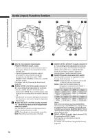
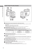
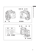
Audio (output) Function Section 34 1 Chapter 2 Parts and their Functions 2 56 7 1 MONITOR SELECT (audio channel) CH1/2 / CH3/4 selector switch Use this switch to select the audio channel whose signals are output to the speakers, earphones or AUDIO OUT connector. CH1/2: Signals on Audio Channels 1 and 2 are output. CH3/4: Signals on Audio Channels 3 and 4 are output. The channel indications on the display window and on the audio level meter in the viewfinder are synchronised with this selector switch. 2 MONITOR SELECT (audio selection) CH1/3 / ST / CH2/4 selector switch In combination with the MONITOR SELECT CH1/2 / CH3/4 switch, select the audio signal output to the speakers and earphones, and from the AUDIO OUT connector. MONITOR SELECT (Left) MONITOR SELECT (Right) CH1/2 CH3/4 CH1/3 Audio Channel 1 Audio Channel 3 MONITOR SELECT ST Stereo signals from Audio Channels 1 and 2 Stereo signals from Audio Channels 3 and 4 CH2/4 Audio Channel 2 Audio Channel 4 3 MONITOR/ALARM (volume) control Used to control the volume of sound output from the monitor speakers and earphones. It also adjusts the alarm sound volume. 4 Speakers The speakers output EE sound during recording, and reproduced sound during playback. The speakers emit an alarm sound when the warning lamp blinks and/or the indicator activates. EE sound and playback sound are not output during alarm sound output. When the PHONES jack is connected with earphones, sound from the speaker is automatically muted. 5 PHONES (earphones) jack (mini jack) This connector is designed for audio monitoring (stereo) earphones. When earphones are connected, sound from the speakers is automatically muted. 6 DC OUT (DC power supply) output socket This output socket is designed for 12-VDC. It provides a maximum current of 1.5 A. 7 AUDIO OUT connector • This connector outputs audio signals recorded on Channels 1/2 or 3/4. • Output signals are selected with the MONITOR SELECT CH1/2 / CH3/4 selector switch. 18
-
 1
1 -
2
-
3
-
4
-
5
-
6
-
7
-
8
-
9
-
10
-
11
-
12
-
 13
13 -
 14
14 -
 15
15 -
 16
16 -
 17
17 -
 18
18 -
 19
19 -
 20
20 -
 21
21 -
 22
22 -
 23
23 -
24
-
25
-
26
-
27
-
28
-
29
-
30
-
31
-
32
-
33
-
34
-
35
-
36
-
37
-
38
-
39
-
40
-
41
-
42
-
43
-
44
-
45
-
46
-
47
-
48
-
49
-
50
-
51
-
52
-
53
-
54
-
55
-
56
-
57
-
58
-
59
-
60
-
61
-
62
-
63
-
64
-
65
-
66
-
67
-
68
-
69
-
70
-
71
-
72
-
73
-
74
-
75
-
76
-
77
-
78
-
79
-
80
-
81
-
82
-
83
-
84
-
85
-
86
-
87
-
88
-
89
-
90
-
91
-
92
-
93
-
94
-
95
-
96
-
97
-
98
-
99
-
100
-
101
-
102
-
103
-
104
-
105
-
106
-
107
-
108
-
109
-
110
-
111
-
112
-
113
-
114
-
115
-
116
-
117
-
118
-
119
-
120
-
121
-
122
-
123
-
124
-
125
-
126
-
127
-
128
-
129
-
130
-
131
-
132
-
133
-
134
-
135
-
136
-
137
-
138
-
139
-
140
-
141
-
142
-
143
-
144
-
145
-
146
-
147
-
148
-
149
-
150
-
151
-
152
 |
 |
