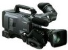
Panasonic HPX500 Operating Instructions - Page 22
Shooting and Recording/Playback, Function recording, P2 CARD ACCESS LED - lens
 |
UPC - 791871302965
View all Panasonic HPX500 manuals
Add to My Manuals
Save this manual to your list of manuals |
Page 22 highlights
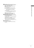
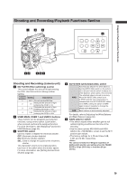
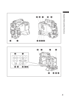
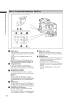
Chapter 2 Parts and their Functions Shooting and Recording/Playback Function Section (recording) 10 REC START/STOP button Pressing this button starts recording, pressing again stops recording. This button has the same function as the VTR button at the lens. When pressed in the MCR mode, the camera automatically switches to the CAMERA mode and starts recording. 11 SAVE switch This switch selects the power saving mode. ON: Forcibly turns off the LCD. OFF: LCD is on. The operating status display in the viewfinder goes off when the SAVE switch is set to ON. But it remains on during special recording. 12 OUTPUT CHARACTER switch This switch controls the superimposition of characters onto the video output (VIDEO OUT, COMPONENT OUT and SDI OUT) to indicate status or menus. ON: Superimposes characters. OFF: Does not superimpose characters. 13 REW (fast-reverse) button During pause, this button performs fast-reverse playback. During playback, it fast-reverses playback at about 4× normal speed. If this button is pressed when playback is paused, the beginning of the clip being played is located in pause mode (cue-up mode). 14 FF (fast forward) button During pause, this button performs fast playback. During playback, it performs fast playback at about 4× normal speed. If this button is pressed when playback is paused, the beginning of the next clip is located in pause mode (cue-up mode). 15 ■STOP button This button stops playback. The menu cursor moves in the thumbnail display. 16 PLAY button This button is used to view playback using the viewfinder screen or a color video monitor. 17 STILL (pause) button Press to pause playback. 18 REC buttons (red and white) Press the red and white buttons simultaneously to start recording the 1394 input signal and press the STOP button to stop recording. To record 1394 input signals, be sure to set the MCR format to the input signal format before starting recording. Do not change the format or terminate signal input during recording. 19 P2 CARD ACCESS LED This LED indicates the recording and playback status of each card. For details, refer to [P2 CARD ACCESS LED and status of P2 cards] (page 32). 20 Slide lock button Used to open the slide-out door for inserting P2 cards. While depressing this button, slide the door to the left. 22 21 USB 2.0 connector Connect a USB 2.0 cable to this connector. Select USB DEVICE under the menu option PC MODE in the screen to send data via the USB 2.0 connector. The camera cannot be used for recording, playback or clip operations when this function is used. For details, refer to [Connecting to External Devices Using USB2.0 Port (PC mode)] (page 131). 22 GENLOCK IN connector This connector inputs a reference signal when the camera unit is gen-locked, or when the time code is externally locked. • The reference signal must be a Y signal (1080/60i, 720/60P, 1080/50i or 720/50P) (HD) or a composite signal (480/60i or 576/50i). • GENLOCK cannot be engaged during playback. 23 REMOTE (remote control) connector By connecting the extension control unit AJRC10G (optional accessory), some functions of the camera can be remote-controlled. For details, refer to [Connecting the AJ-RC10G Extension Controller] (page 102). 24 VIDEO OUT (video signal output) connector This connector outputs video signals. • In HD mode, down-converted composite video signals are output. • Use the DOWNCON MODE in the setup menu DISPLAY SETUP screen to change output. (The factory setting is LETTER BOX.) 13 to 18 work only in MCR mode. 25 SD memory card insertion slot Insert an SD memory card (optional accessory) in this slot. It is used for uploading meta data as well as for reading and writing USER files and SCENE files. ■SD memory card precautions • Use only cards that conform to the SD card standard or the SDHC standard in this camera. • Multimedia cards (MMC) cannot be used. (Use of such cards may prevent recording.) • Be sure to use mini SD card adapter only when using mini SD cards. (Note that this camera will not operate normally when a mini SD adapter is installed without also inserting a card. Be sure to insert a card when an adapter is installed.) • Use of Panasonic SD/SDHC memory cards and mini SD cards is recommended. Be sure to format such cards in this camera. • To format a memory card on a PC, use the dedicated software that can be downloaded from the support site listed below. https : / / ew w.pavc.panasonic.co.jp / pro -av / • This camera supports 8 MB, 16 MB, 32 MB, 64 MB, 128 MB, 256 MB, 512 MB, 1 GB and 2 GB SD memory cards and 4 GB SDHC memory cards. • For the latest information not available in the Operating Instructions, visit the P2 Support site at the above Web site.
-
 1
1 -
2
-
3
-
4
-
5
-
6
-
7
-
8
-
9
-
10
-
11
-
12
-
13
-
14
-
15
-
16
-
 17
17 -
 18
18 -
 19
19 -
 20
20 -
 21
21 -
 22
22 -
 23
23 -
 24
24 -
 25
25 -
 26
26 -
 27
27 -
28
-
29
-
30
-
31
-
32
-
33
-
34
-
35
-
36
-
37
-
38
-
39
-
40
-
41
-
42
-
43
-
44
-
45
-
46
-
47
-
48
-
49
-
50
-
51
-
52
-
53
-
54
-
55
-
56
-
57
-
58
-
59
-
60
-
61
-
62
-
63
-
64
-
65
-
66
-
67
-
68
-
69
-
70
-
71
-
72
-
73
-
74
-
75
-
76
-
77
-
78
-
79
-
80
-
81
-
82
-
83
-
84
-
85
-
86
-
87
-
88
-
89
-
90
-
91
-
92
-
93
-
94
-
95
-
96
-
97
-
98
-
99
-
100
-
101
-
102
-
103
-
104
-
105
-
106
-
107
-
108
-
109
-
110
-
111
-
112
-
113
-
114
-
115
-
116
-
117
-
118
-
119
-
120
-
121
-
122
-
123
-
124
-
125
-
126
-
127
-
128
-
129
-
130
-
131
-
132
-
133
-
134
-
135
-
136
-
137
-
138
-
139
-
140
-
141
-
142
-
143
-
144
-
145
-
146
-
147
-
148
-
149
-
150
-
151
-
152
 |
 |
