Panasonic HPX500 Operating Instructions - Page 16
Audio (input) Function AUDIO LEVEL CH3/CH 4 audio channel 3 - ag manual
 |
UPC - 791871302965
View all Panasonic HPX500 manuals
Add to My Manuals
Save this manual to your list of manuals |
Page 16 highlights
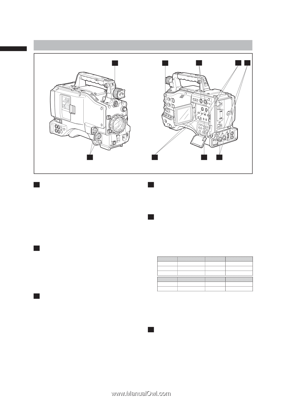
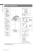
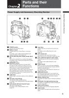
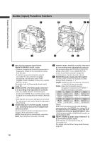
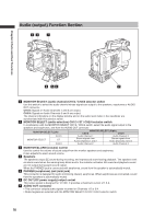
Audio (input) Function Section 9 8 2 37 Chapter 2 Parts and their Functions 1 4 5 6 1 MIC IN (microphone input) jacks FRONT1/FRONT2 (XLR, 3-pin) • Connect microphones (optional accessories) to these jacks. Power for the microphone comes from this jack. • A phantom-powered microphone may be connected. To use a phantom-powered microphone, set the menu option F.MIC POWER1/F.MIC POWER2 to ON in the screen. For details, refer to [Preparing for Audio Input] (page 98). 2 AUDIO LEVEL CH1/CH2 (audio channel 1 & 2 recording level adjustment) controls • With the AUDIO SELECT CH1/CH2 switch positioned to [MAN], these controls can be used to adjust the recording levels for Audio Channels 1/2. • Note that the controls are designed to be locked. For adjustment, each control must be depressed while turning. 3 AUDIO SELECT CH1/CH2 (audio channel 1 & 2 automatic/manual level adjustment selector) switch Use this switch to select recording level control mode for Audio Channels 1 and 2. AUTO: Recording level automatically controlled. MAN: Recording level manually controlled. 4 AUDIO LEVEL CH3/CH 4 (audio channel 3 & 4 recording level adjustment) controls Set the menu option AUTO LEVEL CH3/AUTO LEVEL CH4 to OFF in the screen to use these controls to adjust the recording level of audio channels 3 and 4. 5 AUDIO IN (audio input selector) switch Use this switch to select the signals recorded through Audio Channels 1 - 4. FRONT: Signal from the microphone connected to the MIC IN jack is recorded. REAR: Signal from the audio device or microphone connected to the REAR 1/ REAR 2 connector is recorded. CH1 Input CH2 Input FRONT1 FRONT1 jack FRONT FRONT2 jack FRONT2 FRONT2 jack REAR REAR REAR1 jack - REAR2 jack - CH3 FRONT REAR Input FRONT1 jack REAR1 jack CH4 FRONT REAR Input FRONT2 jack REAR2 jack With a front microphone (such as AG-MC200G) connected only to the FRONT2 jack, setting CH1 of the AUDIO IN switch to FRONT2, setting CH2-CH4 to FRONT and setting the MONITOR SELECT CH1/2 / CH3/4 selector switch to CH3/CH4 will result in no sound output to CH3. 6 REAR 1/REAR 2 (audio input channel 1 & 2) connectors (XLR, 3-pin) Audio devices or a microphone may be connected here. For details, refer to [When Using Audio Devices] (page 99). 16
-
 1
1 -
2
-
3
-
4
-
5
-
6
-
7
-
8
-
9
-
10
-
 11
11 -
 12
12 -
 13
13 -
 14
14 -
 15
15 -
 16
16 -
 17
17 -
 18
18 -
 19
19 -
 20
20 -
 21
21 -
22
-
23
-
24
-
25
-
26
-
27
-
28
-
29
-
30
-
31
-
32
-
33
-
34
-
35
-
36
-
37
-
38
-
39
-
40
-
41
-
42
-
43
-
44
-
45
-
46
-
47
-
48
-
49
-
50
-
51
-
52
-
53
-
54
-
55
-
56
-
57
-
58
-
59
-
60
-
61
-
62
-
63
-
64
-
65
-
66
-
67
-
68
-
69
-
70
-
71
-
72
-
73
-
74
-
75
-
76
-
77
-
78
-
79
-
80
-
81
-
82
-
83
-
84
-
85
-
86
-
87
-
88
-
89
-
90
-
91
-
92
-
93
-
94
-
95
-
96
-
97
-
98
-
99
-
100
-
101
-
102
-
103
-
104
-
105
-
106
-
107
-
108
-
109
-
110
-
111
-
112
-
113
-
114
-
115
-
116
-
117
-
118
-
119
-
120
-
121
-
122
-
123
-
124
-
125
-
126
-
127
-
128
-
129
-
130
-
131
-
132
-
133
-
134
-
135
-
136
-
137
-
138
-
139
-
140
-
141
-
142
-
143
-
144
-
145
-
146
-
147
-
148
-
149
-
150
-
151
-
152
 |
 |