Panasonic HPX500 Operating Instructions - Page 72
Errors, Camera status display, USER buttons assignment information (at mode check)
 |
UPC - 791871302965
View all Panasonic HPX500 manuals
Add to My Manuals
Save this manual to your list of manuals |
Page 72 highlights
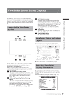
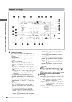
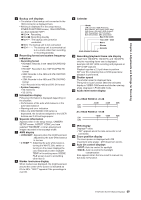
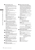
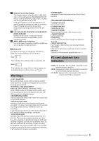
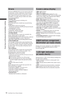
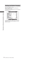
Chapter 4 Adjustments and Settings for Recording Errors These are displayed when an error occurs in the unit, P2 card, tape, or other component. If the problem is not fixed by turning the power off and then on again, either replace the card or tape based on the error information, or consult with your dealer as to which one is to be purchased. • CANNOT REC This is displayed during a recording error. • CANNOT PLAY This is displayed when trouble has occurred during playback. • CARD ERR (1) (2) (3) (4) (1/2/3/4): Trouble has occurred in the P2 card found in the slot indicated by the number. • CLIP ERROR: clip trouble • UPDATING: Reading card data • ERROR: other type of trouble • SYSTEM ERROR This is displayed when trouble has occurred in the system. Switch ON the power again. • P2 MICON ERROR: No P2 microcomputer response • P2 CONTROL ERROR: Trouble in P2 control • REC RAM OVERFLOW: Recording RAM overflow • TURN POWER OFF This message indicates that an abnormal event has occurred, for example, that a card has been removed during access or that a change in system frequency has been made. Turn the power off and then turn it back on again. • REC WARNING This is displayed when trouble has occurred during recording. Carry out recording once again. If the warning persists, consult your dealer. • CARD ERR (1) (2) (3) (4) (1/2/3/4): Trouble has occurred in the P2 card found in the slot indicated by the number. ●If the warning continues, turn off the power. ●If the warning appears even when recording is carried out again, replace the card with another one. • ERROR: Other type of trouble • 1394 This is displayed when trouble has occurred in the 1394 connections or signals. • 1394 INITIAL ERROR: Connection error • 1394 INPUT ERROR: Input error • 1394 INPUT ERROR (OTHER FORMAT): (Wrong input format) • LOW BATTERY: Indicates that the battery is exhausted. Camera status display • AWB: AWB indicator • ABB: ABB indicator • AWB P3.2 K/AWB P5.6K: Displays the color temperature assigned to PRST when the WHITE BAL switch is set to PRST. Also displayed when AWB is performed in the PRST position. • GAIN **dB: Displayed when GAIN is switched. • BACK LIGHT (OFF): Displayed during iris control when back light status is changed by pressing the user button to which BACK LIGHT is assigned. • SPOT LIGHT (OFF): Displayed during iris control when back light status is changed by pressing the user button to which SPOT LIGHT is assigned. • SHUTTER 1/**** (OFF): Displayed when the shutter speed is changed. • SCENE ******: Displays the name of a scene file selected by turning the SCENE FILE dial. • ND NG: Displayed when the ND filter is not working normally. • AUTO KNEE (ON/OFF): Displayed when changing the AUTO KNEE switch position. USER buttons assignment information (at mode check) Displays the function assigned to each USER button. For details, see [Assigning Functions to USER buttons] (page 55). ! LED light indication (at mode check) Indicates why an ! LED is lit according to setting menu VF! LED screen settings. • GAIN: Indicates the camera is using a gain value other than 0 dB. • AWB: Indicates that the WHITE BAL switch is set to PRST. • SHUT: Indicates the electronic shutter is operating. • FILT: Appears when the filter set by menu is met. • EXT: Indicates when the lens extender is inserted. 72 Viewfinder Screen Status Displays
-
 1
1 -
2
-
3
-
4
-
5
-
6
-
7
-
8
-
9
-
10
-
11
-
12
-
13
-
14
-
15
-
16
-
17
-
18
-
19
-
20
-
21
-
22
-
23
-
24
-
25
-
26
-
27
-
28
-
29
-
30
-
31
-
32
-
33
-
34
-
35
-
36
-
37
-
38
-
39
-
40
-
41
-
42
-
43
-
44
-
45
-
46
-
47
-
48
-
49
-
50
-
51
-
52
-
53
-
54
-
55
-
56
-
57
-
58
-
59
-
60
-
61
-
62
-
63
-
64
-
65
-
66
-
 67
67 -
 68
68 -
 69
69 -
 70
70 -
 71
71 -
 72
72 -
 73
73 -
 74
74 -
 75
75 -
 76
76 -
 77
77 -
78
-
79
-
80
-
81
-
82
-
83
-
84
-
85
-
86
-
87
-
88
-
89
-
90
-
91
-
92
-
93
-
94
-
95
-
96
-
97
-
98
-
99
-
100
-
101
-
102
-
103
-
104
-
105
-
106
-
107
-
108
-
109
-
110
-
111
-
112
-
113
-
114
-
115
-
116
-
117
-
118
-
119
-
120
-
121
-
122
-
123
-
124
-
125
-
126
-
127
-
128
-
129
-
130
-
131
-
132
-
133
-
134
-
135
-
136
-
137
-
138
-
139
-
140
-
141
-
142
-
143
-
144
-
145
-
146
-
147
-
148
-
149
-
150
-
151
-
152
 |
 |