Panasonic HPX500 Operating Instructions - Page 135
DVCPRO/DV Connection via IEEE1394 Connector, Recording DVCPRO/DV signals input to 1394 connector
 |
UPC - 791871302965
View all Panasonic HPX500 manuals
Add to My Manuals
Save this manual to your list of manuals |
Page 135 highlights
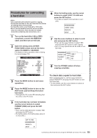
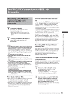
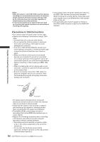
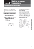
Chapter 8 Connecting to External Devices DVCPRO/DV Connection via IEEE1394 Connector Recording DVCPRO/DV signals input to 1394 connector 1 Connect a 1394 cable. For details, see [Precautions in 1394 Connections] (page 136). • Make sure that the signal format of the camera and the connected device is the same. 2 To input via the IEEE1394 interface, enter MCR mode and turn off thumbnails. • Input signals that have the same format as the setting menu MCR FORMAT and 480i (576i) MCR MODE to the IEEE1394 interface. A signal in a different format will not be correctly recorded on a P2 card. Video and audio recording and EE type video and audio of signal inputs other than 1x speed playback signals may not work. For details, see [Errors] (page 72). • Audio signal inputs are input signals from the 1394 connector. • 32 kHz/4CH (12 bit) audio signals input via the IEEE1394 interface are recorded as 48 kHz/4CH (16 bit) on a P2 card. • It is not possible to use the GENLOCK IN connector to synchronize to an external reference signal. • Signals output from the VIDEO OUT or AUDIO OUT connectors differ from actual input signals. Use such signals for monitoring. • The following functions do not operate. • Pre-recording function • Loop recording function • Interval recording and one shot recording function • Inputs via the 1394 interface are not available when 720P/24PN, 30PN or 25PN are selected in the setting menu MCR FORMAT. Time Code and User Bits • When input from the IEEE1394 interface is selected, the time code or user bits input to the TC IN connector cannot be recorded on a P2 card. • When input from the IEEE1394 interface is selected, time code output from the TC OUT connector is not synchronized to the video signal output from the VIDEO OUT connector. Subcode area time codes and user bits • When input from the IEEE1394 interface is selected, or the TCG switch is set to F-RUN and the menu option F-RUN TC SLAVE in the RECORDING SETUP screen is set to 1394, the time code of the subcode area input from the 1394 connector can be recorded on a P2 card. • To record user bits input form the 1394 connector on a P2 card, set the setting menu 1394 UB REGEN in the RECORDING SETUP screen to ON. VAUX area time codes and user bits When input from the IEEE1394 interface is selected, time code and user bits of the VAUX area input from the 1394 connector is recorded on a P2 card regardless of camera menu settings and switch positions. Recording UMID (Unique Material Identifier) data When input from the IEEE1394 interface is selected, UMID data input via the 1394 connector is recorded on a P2 card. When no UMID data is available, the camera generates and records such data. UMID data is not recorded when the camera is operating in the DV mode. Control of external devices through 1394 connection Using the 1394 interface to connect an external device for backup recording allows the operator to control start and stop operation of backup recording from the camera. 1 Connect a 1394 cable (DV cable). For details, see [Precautions in 1394 Connections] (page 136). • Set 1394 CONTROL in the setting menu OTHER FUNCTIONS screen to BOTH. 2 Use the setting menu 1394 CMD SEL (OTHER FUNCTIONS) to select the command for terminating recording that external devices receive. For details on menu operation, refer to [Using the menus] (page 116). 135 DVCPRO/DV Connection via IEEE1394 Connector
-
 1
1 -
2
-
3
-
4
-
5
-
6
-
7
-
8
-
9
-
10
-
11
-
12
-
13
-
14
-
15
-
16
-
17
-
18
-
19
-
20
-
21
-
22
-
23
-
24
-
25
-
26
-
27
-
28
-
29
-
30
-
31
-
32
-
33
-
34
-
35
-
36
-
37
-
38
-
39
-
40
-
41
-
42
-
43
-
44
-
45
-
46
-
47
-
48
-
49
-
50
-
51
-
52
-
53
-
54
-
55
-
56
-
57
-
58
-
59
-
60
-
61
-
62
-
63
-
64
-
65
-
66
-
67
-
68
-
69
-
70
-
71
-
72
-
73
-
74
-
75
-
76
-
77
-
78
-
79
-
80
-
81
-
82
-
83
-
84
-
85
-
86
-
87
-
88
-
89
-
90
-
91
-
92
-
93
-
94
-
95
-
96
-
97
-
98
-
99
-
100
-
101
-
102
-
103
-
104
-
105
-
106
-
107
-
108
-
109
-
110
-
111
-
112
-
113
-
114
-
115
-
116
-
117
-
118
-
119
-
120
-
121
-
122
-
123
-
124
-
125
-
126
-
127
-
128
-
129
-
 130
130 -
 131
131 -
 132
132 -
 133
133 -
 134
134 -
 135
135 -
 136
136 -
 137
137 -
 138
138 -
 139
139 -
 140
140 -
141
-
142
-
143
-
144
-
145
-
146
-
147
-
148
-
149
-
150
-
151
-
152
 |
 |
