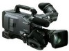
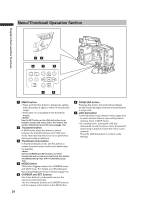
Panasonic HPX500 Operating Instructions - Page 25
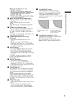
Time Code TC OUT connector BNC - time code to time of day
 |
UPC - 791871302965
View all Panasonic HPX500 manuals
Add to My Manuals
Save this manual to your list of manuals |
Page 25 highlights
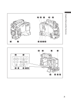
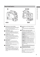
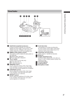
Time Code Section 2 465 Chapter 2 Parts and their Functions 13 78 1 GENLOCK IN connector (BNC) This connector is used to input a reference signal before the camera unit is gen-locked, or before the time code is externally locked. For details, refer to [Externally Locking the Time Code] (page 64). 2 TC IN connector (BNC) This connector is used to input a reference time code when you externally lock the time code. For details, refer to [Externally Locking the Time Code] (page 64). 3 TC OUT connector (BNC) When you inter-lock the time code of the AGHPX500P/E with that of an external device this must be connected with the time code input (TC IN) connector of the external device. For details, refer to [Outputting the time code externally] (page 65). 4 HOLD button Pressing this button freezes the time data indication on the counter. Note that time code generation continues. Pressing the button again reactivates the counter. This function is used to ascertain the time code or CTL count of a particular recorded scene. 5 RESET button Use this button to reset the counter value on the time code display to 0:00:00. When the TCG switch is positioned at [SET] and the setting menus TC PRESET screen and UB PRESET screen are open, press this button to reset all set values to 0 and press the SET button to preset. 6 COUNTER (counter display selector) button The LCD monitor and the viewfinder show the counter value, time code, user bit and frame rate data. 7 TCG (time code selector) switch This switch is used to specify the stepping mode for the built-in time code generator. Select this position to continuously advance the time code independently of F-RUN the P2 card recording status. Use this mode to synchronise the time code with the time of day, or to externally lock the SET R-RUN time code. Select this position to set the time code and/or user bits. Select this position to advance the time code only during recording. The time code is continuously recorded during normal recording. But deleting clips and continuing recording of clips at a frame rate of 24P or 24PA that have been recorded at any other frame rate may break the sequence of time code recording. Always use the CURSOR and SET buttons to set the time code and user bits. The JOG dial button cannot be used for this purpose. 8 CURSOR and SET buttons Use these buttons to set the time code and user bits. The four triangular buttons are the CURSOR buttons, and the center rectangular one is the SET button. For guidance in setting the time code and user bits, see [Setting Time Data] (page 58). 25
-
 1
1 -
2
-
3
-
4
-
5
-
6
-
7
-
8
-
9
-
10
-
11
-
12
-
13
-
14
-
15
-
16
-
17
-
18
-
19
-
 20
20 -
 21
21 -
 22
22 -
 23
23 -
 24
24 -
 25
25 -
 26
26 -
 27
27 -
 28
28 -
 29
29 -
 30
30 -
31
-
32
-
33
-
34
-
35
-
36
-
37
-
38
-
39
-
40
-
41
-
42
-
43
-
44
-
45
-
46
-
47
-
48
-
49
-
50
-
51
-
52
-
53
-
54
-
55
-
56
-
57
-
58
-
59
-
60
-
61
-
62
-
63
-
64
-
65
-
66
-
67
-
68
-
69
-
70
-
71
-
72
-
73
-
74
-
75
-
76
-
77
-
78
-
79
-
80
-
81
-
82
-
83
-
84
-
85
-
86
-
87
-
88
-
89
-
90
-
91
-
92
-
93
-
94
-
95
-
96
-
97
-
98
-
99
-
100
-
101
-
102
-
103
-
104
-
105
-
106
-
107
-
108
-
109
-
110
-
111
-
112
-
113
-
114
-
115
-
116
-
117
-
118
-
119
-
120
-
121
-
122
-
123
-
124
-
125
-
126
-
127
-
128
-
129
-
130
-
131
-
132
-
133
-
134
-
135
-
136
-
137
-
138
-
139
-
140
-
141
-
142
-
143
-
144
-
145
-
146
-
147
-
148
-
149
-
150
-
151
-
152
 |
 |
