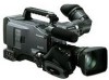
Panasonic HPX500 Operating Instructions - Page 56
Selecting Audio Input Signals and Adjusting Recording Levels, Selecting Audio Input Signals
 |
UPC - 791871302965
View all Panasonic HPX500 manuals
Add to My Manuals
Save this manual to your list of manuals |
Page 56 highlights
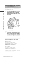
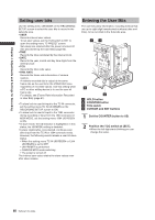
Chapter 4 Adjustments and Settings for Recording Selecting Audio Input Signals and Adjusting Recording Levels This AG-HPX500P/E supports independent fourchannel audio recording in any format (HD or SD). When the AUDIO SELECT CH1/CH2 switch is positioned at [AUTO], the recording levels for Audio Channels 1 and 2 are automatically adjusted. To manually adjust the recording levels, position the switch at [MAN]. Note that the recording levels for Audio Channels 3 and 4 are selected through a menu option. Selecting Audio Input Signals The input signals to be recorded on Audio Channels 1, 2, 3, and 4 are selected with the AUDIO IN switch. For more information, see [Audio (input) Function Section] (page 16). 1 2 Your AG-HPX500P/E is factory-set to perform no recording on Audio Channels 3 and 4 in the DVCPRO and DV formats. To enable four-channel recording, the menu option 25M REC CH SEL on the AUDIO SETUP screen must be set to 4CH. For details on switch settings and the input system, see [AUDIO IN switch] (page 16). • The audio signals recorded on the four channels are output as is (SDI). • With a front microphone (such as AG-MC200G) connected, setting CH1 of the AUDIO IN switch to FRONT2, setting CH2-CH4 to FRONT and setting the MONITOR SELECT CH1/2 / CH3/4 selector switch to CH3 or CH4 will result in no sound output to CH3. Use the AUDIO SETUP screen in the setting menu to make detailed audio settings. AUDIO SETUP FRONT VR CH1 OFF FRONT VR CH2 OFF MIC LOWCUT CH1 OFF MIC LOWCUT CH2 OFF MIC LOWCUT CH3 OFF MIC LOWCUT CH4 OFF LIMITER CH1 OFF LIMITER CH2 OFF PUSH MENU TO RETURN 3 4 1 AUDIO LEVEL CH1/CH2 controls 2 AUDIO SELECT CH1/CH2 switch 3 MONITOR SELECT CH1/3 / ST / CH2/4 selector switch 4 AUDIO IN switch Adjusting Recording Levels To adjust the recording levels for Audio Channels 1 and 2, follow the steps below. 1 Position the MONITOR SELECT CH1/2 / CH3/4-selector switch at CH1/2 so that the audio level meter on the display window will provide CH1 and CH2 indications. Ensure that the channel indications displayed in the window are 1 and 2. 2 Position the AUDIO SELECT CH1/CH2 switch at [MAN]. 56 Selecting Audio Input Signals and Adjusting Recording Levels
-
 1
1 -
2
-
3
-
4
-
5
-
6
-
7
-
8
-
9
-
10
-
11
-
12
-
13
-
14
-
15
-
16
-
17
-
18
-
19
-
20
-
21
-
22
-
23
-
24
-
25
-
26
-
27
-
28
-
29
-
30
-
31
-
32
-
33
-
34
-
35
-
36
-
37
-
38
-
39
-
40
-
41
-
42
-
43
-
44
-
45
-
46
-
47
-
48
-
49
-
50
-
 51
51 -
 52
52 -
 53
53 -
 54
54 -
 55
55 -
 56
56 -
 57
57 -
 58
58 -
 59
59 -
 60
60 -
 61
61 -
62
-
63
-
64
-
65
-
66
-
67
-
68
-
69
-
70
-
71
-
72
-
73
-
74
-
75
-
76
-
77
-
78
-
79
-
80
-
81
-
82
-
83
-
84
-
85
-
86
-
87
-
88
-
89
-
90
-
91
-
92
-
93
-
94
-
95
-
96
-
97
-
98
-
99
-
100
-
101
-
102
-
103
-
104
-
105
-
106
-
107
-
108
-
109
-
110
-
111
-
112
-
113
-
114
-
115
-
116
-
117
-
118
-
119
-
120
-
121
-
122
-
123
-
124
-
125
-
126
-
127
-
128
-
129
-
130
-
131
-
132
-
133
-
134
-
135
-
136
-
137
-
138
-
139
-
140
-
141
-
142
-
143
-
144
-
145
-
146
-
147
-
148
-
149
-
150
-
151
-
152
 |
 |
