Panasonic HPX500 Operating Instructions - Page 15
Parts and their Functions, Power Supply and Accessory Mounting - ag hpx500p manual
 |
UPC - 791871302965
View all Panasonic HPX500 manuals
Add to My Manuals
Save this manual to your list of manuals |
Page 15 highlights
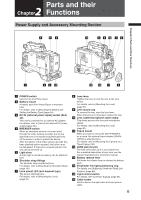
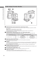
Parts and their 2 Chapter Functions Power Supply and Accessory Mounting Section 6 13 2 16 6 5 14 7 8 Chapter 2 Parts and their Functions 1 4 3 15 10 12 11 9 1 POWER switch Used to turn on/off the power. 2 Battery mount A battery pack from Anton/Bauer is mounted here. For details, refer to [Mounting the Battery and Setting the Battery Type] (page 84). 3 DC IN (external power input) socket (XLR, 4P) This unit is connected to an external AC adapter. For details, refer to [Use of the external DC power supply] (page 86). 4 BREAKER switch When an excessive amount of current is fed through the video camera recorder, due to any abnormal event, the breaker automatically turns off the power in order to protect the device. After the interior of the video camera recorder has been checked and/or repaired, this button must be depressed. If there is no unusual reaction, the unit can be powered-up. 5 Light shoe A video light or similar accessory can be attached here. 6 Shoulder strap fittings The shoulder strap is attached here. For details, refer to [Attaching the Shoulder Strap] (page 101). 7 Lens mount (2/3-inch bayonet type) The lens is attached here. For details, refer to [Mounting the Lens] (page 91). 8 Lens lever Tighten this lever to lock the lens to the lens mount. For details, refer to [Mounting the Lens] (page 91). 9 Lens mount cap To remove the cap, raise the lens lever. When the lens is not mounted, replace the cap. 10 Lens cable/microphone cable clamp This clamp secures the lens and microphone cables. For details, refer to [Mounting the Lens] (page 91). 11 Tripod mount When you want to mount the AG-HPX500P/E on a tripod, the optional tripod adapter (SHANTM700) is attached here. For details, refer to [Mounting the Camera on a Tripod] (page 100). 12 LENS jack (12-pin) The lens connection cord is connected here. For a detailed description of your lens, see the relevant manufacturer's instruction manual. 13 Battery release lever Pull down the release lever to release the battery pack. 14 Viewfinder left-right positioning ring For details, see [Adjusting Viewfinder Right-Left Position] (page 88). 15 Light control switch For details, refer to [Power Supply] (page 84). 16 Cable holder Used to secure the light cable and microphone cable. 15
-
 1
1 -
2
-
3
-
4
-
5
-
6
-
7
-
8
-
9
-
 10
10 -
 11
11 -
 12
12 -
 13
13 -
 14
14 -
 15
15 -
 16
16 -
 17
17 -
 18
18 -
 19
19 -
 20
20 -
21
-
22
-
23
-
24
-
25
-
26
-
27
-
28
-
29
-
30
-
31
-
32
-
33
-
34
-
35
-
36
-
37
-
38
-
39
-
40
-
41
-
42
-
43
-
44
-
45
-
46
-
47
-
48
-
49
-
50
-
51
-
52
-
53
-
54
-
55
-
56
-
57
-
58
-
59
-
60
-
61
-
62
-
63
-
64
-
65
-
66
-
67
-
68
-
69
-
70
-
71
-
72
-
73
-
74
-
75
-
76
-
77
-
78
-
79
-
80
-
81
-
82
-
83
-
84
-
85
-
86
-
87
-
88
-
89
-
90
-
91
-
92
-
93
-
94
-
95
-
96
-
97
-
98
-
99
-
100
-
101
-
102
-
103
-
104
-
105
-
106
-
107
-
108
-
109
-
110
-
111
-
112
-
113
-
114
-
115
-
116
-
117
-
118
-
119
-
120
-
121
-
122
-
123
-
124
-
125
-
126
-
127
-
128
-
129
-
130
-
131
-
132
-
133
-
134
-
135
-
136
-
137
-
138
-
139
-
140
-
141
-
142
-
143
-
144
-
145
-
146
-
147
-
148
-
149
-
150
-
151
-
152
 |
 |
