Panasonic HPX500 Operating Instructions - Page 136
Precautions in 1394 Connections, Connecting to External Devices
 |
UPC - 791871302965
View all Panasonic HPX500 manuals
Add to My Manuals
Save this manual to your list of manuals |
Page 136 highlights
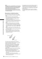
• When the camera is set to REC RUN to perform backup recording on a connected external device, the advance of time code from the 1394 connector will stop when all P2 cards have been fully recorded regardless of whether backup recording continues. • It may not be possible for an external device to back up recording when quick transitions are made between recording and stopping. • Unprocessed video and audio signals are output via the IEEE 1394 interface during special playback. When monitored on another device, these video and audio signals may sound different than when played back on this unit. • CH1 and CH2 audio channel signals for the DV or DVCPRO (25M) format are output via the IEEE1394 interface. Precautions in 1394 Connections • The camera does not supply power via the cable. • Observe the following in connections using a 1394 cable. • Connect this unit to only one other device. • Do not expose the 1394 connector to excessive force when connecting a 1394 cable to avoid damaging the connector. • If an error (1394 INITIAL ERROR) should occur when making a connection, reinsert the 1394 cable or turn the camera off and then turn it back on again. • Make sure that the camera and all connected devices are connected to ground (or connected to a common ground). If the equipment cannot be connected to ground, turn off all connected devices before connecting or disconnecting an IEEE 1394 cable. • When connecting the unit to a device with a 4-pin connector, connect the cable to the 6-pin connector on the camera first. • Be sure to properly connect the 1394 cable to a personal computer with a 6-pin connector. Note that inserting the plug the wrong way round may damage the connector. 6-pin type Chapter 8 Connecting to External Devices 4-pin type • AV signals may be disrupted when connected devices are turned on and off or when the interface cable is connected or disconnected. • It may take the system a few seconds to stabilize after switching input signals or changing modes. Start recording after the system has stabilized. • The AUDIO LEVEL control does not work in recordings that involve IEEE1394 interface input or output signals. • Observe the following precautions when controlling a P2 memory card camera-recorder using PC application software (editing software). • Recording cannot be inserted to a portion within a clip. It can only be appended to the end of the newest clip. • Do not open the thumbnail screen during application software operation as this may prevent normal software operation. 136 DVCPRO/DV Connection via IEEE1394 Connector
-
 1
1 -
2
-
3
-
4
-
5
-
6
-
7
-
8
-
9
-
10
-
11
-
12
-
13
-
14
-
15
-
16
-
17
-
18
-
19
-
20
-
21
-
22
-
23
-
24
-
25
-
26
-
27
-
28
-
29
-
30
-
31
-
32
-
33
-
34
-
35
-
36
-
37
-
38
-
39
-
40
-
41
-
42
-
43
-
44
-
45
-
46
-
47
-
48
-
49
-
50
-
51
-
52
-
53
-
54
-
55
-
56
-
57
-
58
-
59
-
60
-
61
-
62
-
63
-
64
-
65
-
66
-
67
-
68
-
69
-
70
-
71
-
72
-
73
-
74
-
75
-
76
-
77
-
78
-
79
-
80
-
81
-
82
-
83
-
84
-
85
-
86
-
87
-
88
-
89
-
90
-
91
-
92
-
93
-
94
-
95
-
96
-
97
-
98
-
99
-
100
-
101
-
102
-
103
-
104
-
105
-
106
-
107
-
108
-
109
-
110
-
111
-
112
-
113
-
114
-
115
-
116
-
117
-
118
-
119
-
120
-
121
-
122
-
123
-
124
-
125
-
126
-
127
-
128
-
129
-
130
-
 131
131 -
 132
132 -
 133
133 -
 134
134 -
 135
135 -
 136
136 -
 137
137 -
 138
138 -
 139
139 -
 140
140 -
 141
141 -
142
-
143
-
144
-
145
-
146
-
147
-
148
-
149
-
150
-
151
-
152
 |
 |
