HP 1050c Service Manual - Page 246
Tensioner Assembly, For steps 4 to 6, refer to Tensioner Assembly
 |
View all HP 1050c manuals
Add to My Manuals
Save this manual to your list of manuals |
Page 246 highlights
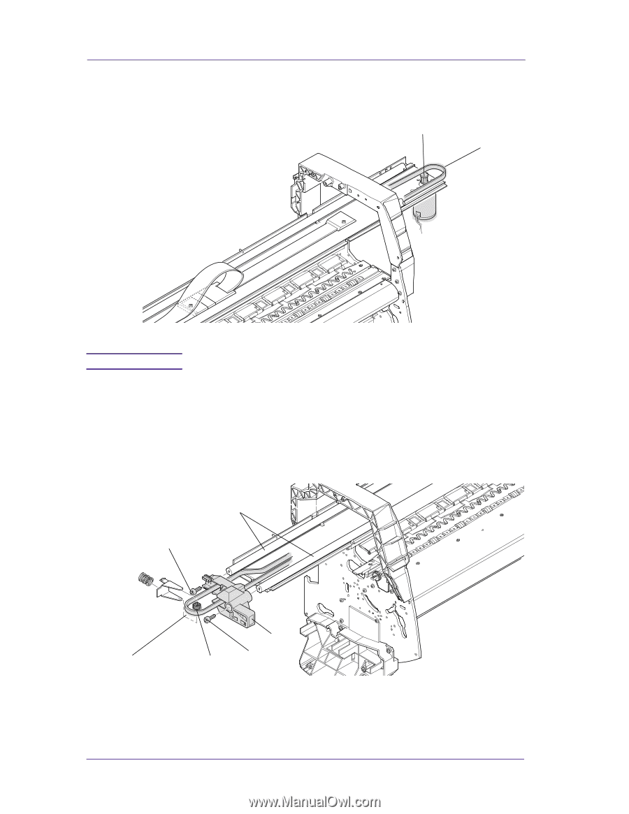
Removal and Installation 3. Remove the belt (item 1) from the belt motor pulley (item 2) on the right hand side of the Printer (refer to Figure 34) 2 1 NOTE Figure 34: Tensioner Assembly For steps 4 to 6, refer to Figure 35. 4. Remove the tensioner pulley (item 1) from the belt (item 2) which is located in the tensioner assembly (item 3). 5. Remove the two T-15 screws (item 4) securing the tensioner assembly to the slider rods (item 5). 6. Remove the tensioner assembly (item 3). 5 4 2 8-38 3 4 1 Figure 35: Tensioner Assembly HP DesignJets 1050C and 1055CM Printers Service Manual
-
 1
1 -
2
-
3
-
4
-
5
-
6
-
7
-
8
-
9
-
10
-
11
-
12
-
13
-
14
-
15
-
16
-
17
-
18
-
19
-
20
-
21
-
22
-
23
-
24
-
25
-
26
-
27
-
28
-
29
-
30
-
31
-
32
-
33
-
34
-
35
-
36
-
37
-
38
-
39
-
40
-
41
-
42
-
43
-
44
-
45
-
46
-
47
-
48
-
49
-
50
-
51
-
52
-
53
-
54
-
55
-
56
-
57
-
58
-
59
-
60
-
61
-
62
-
63
-
64
-
65
-
66
-
67
-
68
-
69
-
70
-
71
-
72
-
73
-
74
-
75
-
76
-
77
-
78
-
79
-
80
-
81
-
82
-
83
-
84
-
85
-
86
-
87
-
88
-
89
-
90
-
91
-
92
-
93
-
94
-
95
-
96
-
97
-
98
-
99
-
100
-
101
-
102
-
103
-
104
-
105
-
106
-
107
-
108
-
109
-
110
-
111
-
112
-
113
-
114
-
115
-
116
-
117
-
118
-
119
-
120
-
121
-
122
-
123
-
124
-
125
-
126
-
127
-
128
-
129
-
130
-
131
-
132
-
133
-
134
-
135
-
136
-
137
-
138
-
139
-
140
-
141
-
142
-
143
-
144
-
145
-
146
-
147
-
148
-
149
-
150
-
151
-
152
-
153
-
154
-
155
-
156
-
157
-
158
-
159
-
160
-
161
-
162
-
163
-
164
-
165
-
166
-
167
-
168
-
169
-
170
-
171
-
172
-
173
-
174
-
175
-
176
-
177
-
178
-
179
-
180
-
181
-
182
-
183
-
184
-
185
-
186
-
187
-
188
-
189
-
190
-
191
-
192
-
193
-
194
-
195
-
196
-
197
-
198
-
199
-
200
-
201
-
202
-
203
-
204
-
205
-
206
-
207
-
208
-
209
-
210
-
211
-
212
-
213
-
214
-
215
-
216
-
217
-
218
-
219
-
220
-
221
-
222
-
223
-
224
-
225
-
226
-
227
-
228
-
229
-
230
-
231
-
232
-
233
-
234
-
235
-
236
-
237
-
238
-
239
-
240
-
 241
241 -
 242
242 -
 243
243 -
 244
244 -
 245
245 -
 246
246 -
 247
247 -
 248
248 -
 249
249 -
 250
250 -
 251
251 -
252
-
253
-
254
-
255
-
256
-
257
-
258
-
259
-
260
-
261
-
262
-
263
-
264
-
265
-
266
-
267
-
268
-
269
-
270
-
271
-
272
-
273
-
274
-
275
-
276
-
277
-
278
-
279
-
280
-
281
-
282
-
283
-
284
-
285
-
286
-
287
-
288
-
289
-
290
-
291
-
292
-
293
-
294
-
295
-
296
-
297
-
298
-
299
-
300
-
301
-
302
-
303
-
304
-
305
-
306
-
307
-
308
-
309
-
310
-
311
-
312
-
313
-
314
-
315
-
316
-
317
-
318
-
319
-
320
-
321
-
322
 |
 |
Removal and Installation
8-38
HP DesignJets 1050C and 1055CM Printers Service Manual
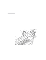
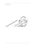
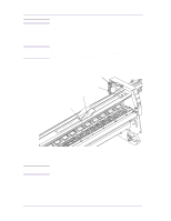
3.
Remove the belt (item 1) from the belt motor pulley (item 2) on the
right hand side of the Printer (refer to Figure 34)
Figure 34: Tensioner Assembly
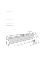
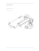
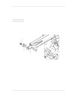
NOTE
For steps 4 to 6, refer to Figure 35.
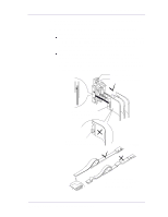
4.
Remove the tensioner pulley (item 1) from the belt (item 2) which is
located in the tensioner assembly (item 3).
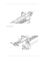
5.
Remove the two T-15 screws (item 4) securing the tensioner
assembly to the slider rods (item 5).
6.
Remove the tensioner assembly (item 3).
Figure 35: Tensioner Assembly
1
2
1
2
3
4
5
4