HP 1050c Service Manual - Page 272
Paper Entry Assembly
 |
View all HP 1050c manuals
Add to My Manuals
Save this manual to your list of manuals |
Page 272 highlights
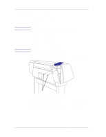
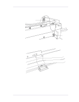
Removal and Installation Paper Entry Assembly Refer to Figure 69 to Figure 71. WARNING Removal Switch off the printer and remove the power cord. 1. 1.Remove the following: 1. "Left Hand Cover" see page 8-13. 2. "Left Hand Trim" see page 8-18. 3. "Ink Supply System Assembly" see page 8-19. 4. "Clutch Assembly and Miscellaneous Parts" see page 8-21. 2. Remove the T-15 screws (item 2) securing the entry roller (item 1) to the left hand chassis (refer to Figure 69). Pull out the left side of the entry roller first and then remove completely. 1 2 C607423 Figure 69: Entry Roller 8-64 HP DesignJets 1050C and 1055CM Printers Service Manual
-
 1
1 -
2
-
3
-
4
-
5
-
6
-
7
-
8
-
9
-
10
-
11
-
12
-
13
-
14
-
15
-
16
-
17
-
18
-
19
-
20
-
21
-
22
-
23
-
24
-
25
-
26
-
27
-
28
-
29
-
30
-
31
-
32
-
33
-
34
-
35
-
36
-
37
-
38
-
39
-
40
-
41
-
42
-
43
-
44
-
45
-
46
-
47
-
48
-
49
-
50
-
51
-
52
-
53
-
54
-
55
-
56
-
57
-
58
-
59
-
60
-
61
-
62
-
63
-
64
-
65
-
66
-
67
-
68
-
69
-
70
-
71
-
72
-
73
-
74
-
75
-
76
-
77
-
78
-
79
-
80
-
81
-
82
-
83
-
84
-
85
-
86
-
87
-
88
-
89
-
90
-
91
-
92
-
93
-
94
-
95
-
96
-
97
-
98
-
99
-
100
-
101
-
102
-
103
-
104
-
105
-
106
-
107
-
108
-
109
-
110
-
111
-
112
-
113
-
114
-
115
-
116
-
117
-
118
-
119
-
120
-
121
-
122
-
123
-
124
-
125
-
126
-
127
-
128
-
129
-
130
-
131
-
132
-
133
-
134
-
135
-
136
-
137
-
138
-
139
-
140
-
141
-
142
-
143
-
144
-
145
-
146
-
147
-
148
-
149
-
150
-
151
-
152
-
153
-
154
-
155
-
156
-
157
-
158
-
159
-
160
-
161
-
162
-
163
-
164
-
165
-
166
-
167
-
168
-
169
-
170
-
171
-
172
-
173
-
174
-
175
-
176
-
177
-
178
-
179
-
180
-
181
-
182
-
183
-
184
-
185
-
186
-
187
-
188
-
189
-
190
-
191
-
192
-
193
-
194
-
195
-
196
-
197
-
198
-
199
-
200
-
201
-
202
-
203
-
204
-
205
-
206
-
207
-
208
-
209
-
210
-
211
-
212
-
213
-
214
-
215
-
216
-
217
-
218
-
219
-
220
-
221
-
222
-
223
-
224
-
225
-
226
-
227
-
228
-
229
-
230
-
231
-
232
-
233
-
234
-
235
-
236
-
237
-
238
-
239
-
240
-
241
-
242
-
243
-
244
-
245
-
246
-
247
-
248
-
249
-
250
-
251
-
252
-
253
-
254
-
255
-
256
-
257
-
258
-
259
-
260
-
261
-
262
-
263
-
264
-
265
-
266
-
 267
267 -
 268
268 -
 269
269 -
 270
270 -
 271
271 -
 272
272 -
 273
273 -
 274
274 -
 275
275 -
 276
276 -
 277
277 -
278
-
279
-
280
-
281
-
282
-
283
-
284
-
285
-
286
-
287
-
288
-
289
-
290
-
291
-
292
-
293
-
294
-
295
-
296
-
297
-
298
-
299
-
300
-
301
-
302
-
303
-
304
-
305
-
306
-
307
-
308
-
309
-
310
-
311
-
312
-
313
-
314
-
315
-
316
-
317
-
318
-
319
-
320
-
321
-
322
 |
 |
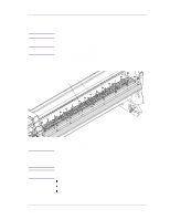
Removal and Installation
8-64
HP DesignJets 1050C and 1055CM Printers Service Manual
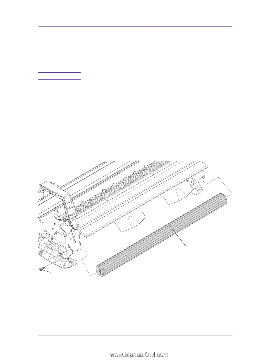
Paper Entry Assembly
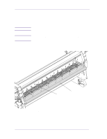
Refer to Figure 69 to Figure 71.
Removal
WARNING
Switch off the printer and remove the power cord.
1.
1.Remove the following:
1.
"Left Hand Cover" see page 8-13.
2.
"Left Hand Trim" see page 8-18.
3.
"Ink Supply System Assembly" see page 8-19.
4.
"Clutch Assembly and Miscellaneous Parts" see page 8-21.
2.
Remove the T-15 screws (item 2) securing the entry roller (item 1)
to the left hand chassis (refer to Figure 69). Pull out the left side of
the entry roller first and then remove completely.
Figure 69: Entry Roller
C607423
2
1