HP 1050c Service Manual - Page 279
Center Guide
 |
View all HP 1050c manuals
Add to My Manuals
Save this manual to your list of manuals |
Page 279 highlights
Removal and Installation Center Guide Refer to Figure 78 to Figure 80. WARNING Removal Switch off the printer and remove the power cord. 1. Remove the following: 1. "Left Hand Cover" see page 8-13. 2. "Right Hand Cover" see page 8-4. 3. "Electronics module" see page 8-25. 4. "Ink Supply System Assembly" see page 8-19. 5. "Clutch assembly" see page 8-21. 6. "Service Station" see page 8-8. 7. "Vacuum Fan" see page 8-11. 2. Lift up the paper entry assembly. 3. Remove the two T-15 screws from the left hand side plate securing the left side of the center guide (refer to Figure 78). 1 Figure 78: Left Hand Center Guide Screws C607433 HP DesignJets 1050C and 1055CM Printers Service Manual 8-71
-
 1
1 -
2
-
3
-
4
-
5
-
6
-
7
-
8
-
9
-
10
-
11
-
12
-
13
-
14
-
15
-
16
-
17
-
18
-
19
-
20
-
21
-
22
-
23
-
24
-
25
-
26
-
27
-
28
-
29
-
30
-
31
-
32
-
33
-
34
-
35
-
36
-
37
-
38
-
39
-
40
-
41
-
42
-
43
-
44
-
45
-
46
-
47
-
48
-
49
-
50
-
51
-
52
-
53
-
54
-
55
-
56
-
57
-
58
-
59
-
60
-
61
-
62
-
63
-
64
-
65
-
66
-
67
-
68
-
69
-
70
-
71
-
72
-
73
-
74
-
75
-
76
-
77
-
78
-
79
-
80
-
81
-
82
-
83
-
84
-
85
-
86
-
87
-
88
-
89
-
90
-
91
-
92
-
93
-
94
-
95
-
96
-
97
-
98
-
99
-
100
-
101
-
102
-
103
-
104
-
105
-
106
-
107
-
108
-
109
-
110
-
111
-
112
-
113
-
114
-
115
-
116
-
117
-
118
-
119
-
120
-
121
-
122
-
123
-
124
-
125
-
126
-
127
-
128
-
129
-
130
-
131
-
132
-
133
-
134
-
135
-
136
-
137
-
138
-
139
-
140
-
141
-
142
-
143
-
144
-
145
-
146
-
147
-
148
-
149
-
150
-
151
-
152
-
153
-
154
-
155
-
156
-
157
-
158
-
159
-
160
-
161
-
162
-
163
-
164
-
165
-
166
-
167
-
168
-
169
-
170
-
171
-
172
-
173
-
174
-
175
-
176
-
177
-
178
-
179
-
180
-
181
-
182
-
183
-
184
-
185
-
186
-
187
-
188
-
189
-
190
-
191
-
192
-
193
-
194
-
195
-
196
-
197
-
198
-
199
-
200
-
201
-
202
-
203
-
204
-
205
-
206
-
207
-
208
-
209
-
210
-
211
-
212
-
213
-
214
-
215
-
216
-
217
-
218
-
219
-
220
-
221
-
222
-
223
-
224
-
225
-
226
-
227
-
228
-
229
-
230
-
231
-
232
-
233
-
234
-
235
-
236
-
237
-
238
-
239
-
240
-
241
-
242
-
243
-
244
-
245
-
246
-
247
-
248
-
249
-
250
-
251
-
252
-
253
-
254
-
255
-
256
-
257
-
258
-
259
-
260
-
261
-
262
-
263
-
264
-
265
-
266
-
267
-
268
-
269
-
270
-
271
-
272
-
273
-
 274
274 -
 275
275 -
 276
276 -
 277
277 -
 278
278 -
 279
279 -
 280
280 -
 281
281 -
 282
282 -
 283
283 -
 284
284 -
285
-
286
-
287
-
288
-
289
-
290
-
291
-
292
-
293
-
294
-
295
-
296
-
297
-
298
-
299
-
300
-
301
-
302
-
303
-
304
-
305
-
306
-
307
-
308
-
309
-
310
-
311
-
312
-
313
-
314
-
315
-
316
-
317
-
318
-
319
-
320
-
321
-
322
 |
 |
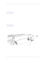
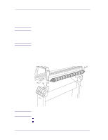
Removal and Installation
8-71
HP DesignJets 1050C and 1055CM Printers Service Manual
Center Guide
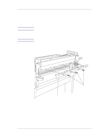
Refer to Figure 78 to Figure 80.
Removal
WARNING
Switch off the printer and remove the power cord.
1.
Remove the following:
1.
"Left Hand Cover" see page 8-13.
2.
"Right Hand Cover" see page 8-4.
3.
"Electronics module" see page 8-25.
4.
"Ink Supply System Assembly" see page 8-19.
5.
"Clutch assembly" see page 8-21.
6.
"Service Station" see page 8-8.
7.
"Vacuum Fan" see page 8-11.
2.
Lift up the paper entry assembly.
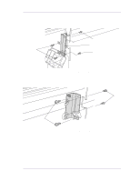
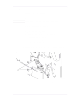
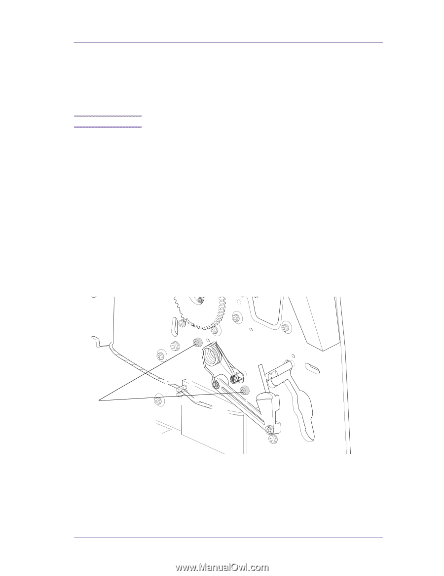
3.
Remove the two T-15 screws from the left hand side plate securing
the left side of the center guide (refer to Figure 78).
Figure 78: Left Hand Center Guide Screws
C607433
1