HP 1050c Service Manual - Page 289
Power Supply Unit PSU - main board
 |
View all HP 1050c manuals
Add to My Manuals
Save this manual to your list of manuals |
Page 289 highlights
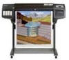
Functional Overview sensor. n Service station: Contains the electronics needed to perform drop detection, a DC motor/encoder for capping, wiping and spitting and a stepper motor for priming. n Front Panel: is the user interface. It consists of an LCD display, a key panel and six LEDs. Power Supply Unit (PSU) The PSU is used to supply the power required by the product in any condition.The PSU provides +5 V, +3.3 V, -15 V and +24 V to the main board with the following maximum output currents: Voltage Maximum Output Current (A) Systems +3.3 +5.0 +24.0 -15.0 12.0 Microprocessor, Memory and digital Logic 3.0 Digital and Analog Logic 13.5 Analog power systems and Carriage Voltage Supply 0.1 Front Panel Auxiliary Voltage The PSU is housed in the electronics enclosure and there are two connections with the main board: voltage supply connection and auxiliary output connection. The voltage supply connection is implemented via a 15 pin connector with 14 wires, this connector supply the +3.3V, +5 V and +24 V voltages and the ground lines to the electronics. The auxiliary output connector provides the -15V voltage, the PSU preset signal and the soft power off signal. PSU preset signal is a logic signal generated by the PSU, when the PSU is in on state this line is in open condition, when the unit is to switch off the signal is grounded at least 3 ms before the +3.3V and +5V outputs are out of regulation. The power off signal is a signal generated by the main electronics and is used to turn off the power supply. When the signal is not actuated the PSU is in on state, when it is grounded by the main electronics then the PSU is switched off. There is an input connector to the supply implemented with a hard switch to provide the input voltage which is in the range 80-264 V. HP DesignJets 1050C and 1055CM Printers Service Manual 10-3
-
 1
1 -
2
-
3
-
4
-
5
-
6
-
7
-
8
-
9
-
10
-
11
-
12
-
13
-
14
-
15
-
16
-
17
-
18
-
19
-
20
-
21
-
22
-
23
-
24
-
25
-
26
-
27
-
28
-
29
-
30
-
31
-
32
-
33
-
34
-
35
-
36
-
37
-
38
-
39
-
40
-
41
-
42
-
43
-
44
-
45
-
46
-
47
-
48
-
49
-
50
-
51
-
52
-
53
-
54
-
55
-
56
-
57
-
58
-
59
-
60
-
61
-
62
-
63
-
64
-
65
-
66
-
67
-
68
-
69
-
70
-
71
-
72
-
73
-
74
-
75
-
76
-
77
-
78
-
79
-
80
-
81
-
82
-
83
-
84
-
85
-
86
-
87
-
88
-
89
-
90
-
91
-
92
-
93
-
94
-
95
-
96
-
97
-
98
-
99
-
100
-
101
-
102
-
103
-
104
-
105
-
106
-
107
-
108
-
109
-
110
-
111
-
112
-
113
-
114
-
115
-
116
-
117
-
118
-
119
-
120
-
121
-
122
-
123
-
124
-
125
-
126
-
127
-
128
-
129
-
130
-
131
-
132
-
133
-
134
-
135
-
136
-
137
-
138
-
139
-
140
-
141
-
142
-
143
-
144
-
145
-
146
-
147
-
148
-
149
-
150
-
151
-
152
-
153
-
154
-
155
-
156
-
157
-
158
-
159
-
160
-
161
-
162
-
163
-
164
-
165
-
166
-
167
-
168
-
169
-
170
-
171
-
172
-
173
-
174
-
175
-
176
-
177
-
178
-
179
-
180
-
181
-
182
-
183
-
184
-
185
-
186
-
187
-
188
-
189
-
190
-
191
-
192
-
193
-
194
-
195
-
196
-
197
-
198
-
199
-
200
-
201
-
202
-
203
-
204
-
205
-
206
-
207
-
208
-
209
-
210
-
211
-
212
-
213
-
214
-
215
-
216
-
217
-
218
-
219
-
220
-
221
-
222
-
223
-
224
-
225
-
226
-
227
-
228
-
229
-
230
-
231
-
232
-
233
-
234
-
235
-
236
-
237
-
238
-
239
-
240
-
241
-
242
-
243
-
244
-
245
-
246
-
247
-
248
-
249
-
250
-
251
-
252
-
253
-
254
-
255
-
256
-
257
-
258
-
259
-
260
-
261
-
262
-
263
-
264
-
265
-
266
-
267
-
268
-
269
-
270
-
271
-
272
-
273
-
274
-
275
-
276
-
277
-
278
-
279
-
280
-
281
-
282
-
283
-
 284
284 -
 285
285 -
 286
286 -
 287
287 -
 288
288 -
 289
289 -
 290
290 -
 291
291 -
 292
292 -
 293
293 -
 294
294 -
295
-
296
-
297
-
298
-
299
-
300
-
301
-
302
-
303
-
304
-
305
-
306
-
307
-
308
-
309
-
310
-
311
-
312
-
313
-
314
-
315
-
316
-
317
-
318
-
319
-
320
-
321
-
322
 |
 |