Intel S2600GZ S2600GZ/GL - Page 100
Front Panel USB Connector, Front Panel Video Connector
 |
View all Intel S2600GZ manuals
Add to My Manuals
Save this manual to your list of manuals |
Page 100 highlights
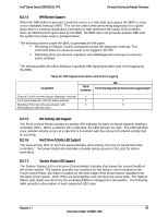
Intel® Server Board S2600GZ/GL TPS On-board Connector/Header Overview Color State Criticality Description CPU Thermal Trip No power good - power fault DIMM failure when there is only 1 DIMM present and hence no good memory present1. Runtime memory uncorrectable error in non-redundant mode. DIMM Thermal Trip or equivalent SSB Thermal Trip or equivalent CPU ERR2 signal asserted BMC\Video memory test failed. (Chassis ID shows blue/solid-on for this condition) Both uBoot BMC FW images are bad. (Chassis ID shows blue/solidon for this condition) 240VA fault Fatal Error in processor initialization: Processor family not identical Processor model not identical Processor core/thread counts not identical Processor cache size not identical Unable to synchronize processor frequency Unable to synchronize QPI link frequency 8.2.2 Front Panel USB Connector The server board includes a 10-pin connector, that when cabled, can provide up to two USB ports to a front panel. On the server board the connector is labeled "FP USB" and is located on the front edge of the board. The following table provides the connector pin-out. Table 32. Front Panel USB Connector Pin-out ("FP USB") Signal Description Pin# Pin# Signal Description P5V_USB_FP 1 2 P5V_USB_FP USB2_P11_F_DN 3 4 USB2_P13_F_DN USB2_P11_F_DP 5 6 USB2_P13_F_DP GROUND 7 8 GROUND 10 TP_USB2_FP_10 8.2.3 Front Panel Video Connector The server board includes a 14-pin header, that when cabled, can provide an alternate video connector to the front panel. On the server board this connector is labeled "FP VIDEO" and is located on the front edge of the board. When a monitor is attached to the front panel video connector, the external video connector located on the back edge of the board is disabled. The following table provides the pin-out for this connector. Table 33. Front Panel Video Connector Pin-out ("FP VIDEO") Signal Description Pin# Pin# Signal Description V_IO_FRONT_R_CONN 1 2 GROUND V_IO_FRONT_G_CONN 3 4 GROUND V_IO_FRONT_B_CONN 5 6 GROUND V_BMC_GFX_FRONT_VSYN 7 8 GROUND V_BMC_GFX_FRONT_HSYN 9 KEY V_BMC_FRONT_DDC_SDA_CONN 11 12 V_FRONT_PRES_N V_BMC_FRONT_DDC_SCL_CONN 13 14 P5V_VID_CONN_FNT Revision 1.1 87 Intel order number G24881-004
-
 1
1 -
2
-
3
-
4
-
5
-
6
-
7
-
8
-
9
-
10
-
11
-
12
-
13
-
14
-
15
-
16
-
17
-
18
-
19
-
20
-
21
-
22
-
23
-
24
-
25
-
26
-
27
-
28
-
29
-
30
-
31
-
32
-
33
-
34
-
35
-
36
-
37
-
38
-
39
-
40
-
41
-
42
-
43
-
44
-
45
-
46
-
47
-
48
-
49
-
50
-
51
-
52
-
53
-
54
-
55
-
56
-
57
-
58
-
59
-
60
-
61
-
62
-
63
-
64
-
65
-
66
-
67
-
68
-
69
-
70
-
71
-
72
-
73
-
74
-
75
-
76
-
77
-
78
-
79
-
80
-
81
-
82
-
83
-
84
-
85
-
86
-
87
-
88
-
89
-
90
-
91
-
92
-
93
-
94
-
 95
95 -
 96
96 -
 97
97 -
 98
98 -
 99
99 -
 100
100 -
 101
101 -
 102
102 -
 103
103 -
 104
104 -
 105
105 -
106
-
107
-
108
-
109
-
110
-
111
-
112
-
113
-
114
-
115
-
116
-
117
-
118
-
119
-
120
-
121
-
122
-
123
-
124
-
125
-
126
-
127
-
128
-
129
-
130
-
131
-
132
-
133
-
134
-
135
-
136
-
137
-
138
-
139
-
140
-
141
-
142
-
143
-
144
-
145
-
146
-
147
-
148
-
149
-
150
-
151
-
152
-
153
-
154
-
155
-
156
-
157
-
158
-
159
-
160
-
161
-
162
-
163
-
164
-
165
-
166
-
167
-
168
-
169
-
170
-
171
-
172
-
173
-
174
-
175
-
176
-
177
-
178
-
179
-
180
-
181
-
182
-
183
-
184
-
185
-
186
-
187
-
188
-
189
-
190
-
191
-
192
-
193
-
194
-
195
-
196
-
197
-
198
-
199
-
200
-
201
-
202
-
203
-
204
-
205
-
206
-
207
-
208
-
209
-
210
-
211
-
212
-
213
-
214
-
215
-
216
-
217
-
218
-
219
-
220
-
221
-
222
-
223
-
224
-
225
-
226
-
227
-
228
-
229
-
230
-
231
-
232
-
233
-
234
-
235
-
236
-
237
-
238
-
239
-
240
-
241
-
242
-
243
-
244
-
245
-
246
-
247
-
248
-
249
-
250
-
251
-
252
-
253
-
254
-
255
-
256
-
257
-
258
-
259
-
260
-
261
-
262
-
263
-
264
 |
 |
