Intel S2600GZ S2600GZ/GL - Page 7

Reset and Recovery Jumpers, Light Guided Diagnostics, Power Supply Specification Guidelines, BIOS - fans

Page 7 highlights

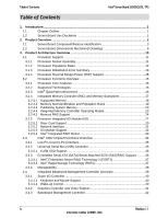
Intel® Server Board S2600GZ/GL TPS Table of Contents 8.3 On-Board Storage Connectors 88 8.3.1 Single Port SATA Only Connectors 88 8.3.2 Multiport Mini-SAS/SATA Connectors 88 8.3.3 Internal Type-A USB Connector 90 8.3.4 Internal 2mm Low Profile eUSB SSD Connector 90 8.4 Fan Connectors...90 8.5 Serial Port Connectors 91 8.6 Other Connectors and Headers 92 9. Reset and Recovery Jumpers 94 10. Light Guided Diagnostics 98 10.1 System ID LED...99 10.2 System Status LED 99 10.3 BMC Boot/Reset Status LED Indicators 101 10.4 Post Code Diagnostic LEDs 102 10.5 12 Volt Stand-By Present LED 102 10.6 Fan Fault LEDs 102 10.7 Memory Fault LEDs 102 10.8 CPU Fault LEDs 102 10.9 System Power Good LED 102 10.10 CATERR LED ...102 11. Power Supply Specification Guidelines 103 11.1 Power Supply DC Output Connector 103 11.2 Power Supply DC Output Specification 104 11.2.1 Output Power/Currents 104 11.2.2 Standby Output 104 11.2.3 Voltage Regulation 104 11.2.4 Dynamic Loading 105 11.2.5 Capacitive Loading 105 11.2.6 Grounding ...105 11.2.7 Closed loop stability 105 11.2.8 Residual Voltage Immunity in Standby mode 105 11.2.9 Common Mode Noise 106 11.2.10 Soft Starting ...106 11.2.11 Zero Load Stability Requirements 106 11.2.12 Hot Swap Requirements 106 11.2.13 Forced Load Sharing 106 11.2.14 Ripple/Noise...106 11.2.15 Timing Requirements 107 12. BIOS Setup Utility...109 12.1 BIOS Setup Operation 109 12.1.1 Entering BIOS Setup 109 12.1.2 Setup Navigation Keyboard Commands 110 Revision 1.1 vii Intel order number G24881-004

  • 1
  • 2
  • 3
  • 4
  • 5
  • 6
  • 7
  • 8
  • 9
  • 10
  • 11
  • 12
  • 13
  • 14
  • 15
  • 16
  • 17
  • 18
  • 19
  • 20
  • 21
  • 22
  • 23
  • 24
  • 25
  • 26
  • 27
  • 28
  • 29
  • 30
  • 31
  • 32
  • 33
  • 34
  • 35
  • 36
  • 37
  • 38
  • 39
  • 40
  • 41
  • 42
  • 43
  • 44
  • 45
  • 46
  • 47
  • 48
  • 49
  • 50
  • 51
  • 52
  • 53
  • 54
  • 55
  • 56
  • 57
  • 58
  • 59
  • 60
  • 61
  • 62
  • 63
  • 64
  • 65
  • 66
  • 67
  • 68
  • 69
  • 70
  • 71
  • 72
  • 73
  • 74
  • 75
  • 76
  • 77
  • 78
  • 79
  • 80
  • 81
  • 82
  • 83
  • 84
  • 85
  • 86
  • 87
  • 88
  • 89
  • 90
  • 91
  • 92
  • 93
  • 94
  • 95
  • 96
  • 97
  • 98
  • 99
  • 100
  • 101
  • 102
  • 103
  • 104
  • 105
  • 106
  • 107
  • 108
  • 109
  • 110
  • 111
  • 112
  • 113
  • 114
  • 115
  • 116
  • 117
  • 118
  • 119
  • 120
  • 121
  • 122
  • 123
  • 124
  • 125
  • 126
  • 127
  • 128
  • 129
  • 130
  • 131
  • 132
  • 133
  • 134
  • 135
  • 136
  • 137
  • 138
  • 139
  • 140
  • 141
  • 142
  • 143
  • 144
  • 145
  • 146
  • 147
  • 148
  • 149
  • 150
  • 151
  • 152
  • 153
  • 154
  • 155
  • 156
  • 157
  • 158
  • 159
  • 160
  • 161
  • 162
  • 163
  • 164
  • 165
  • 166
  • 167
  • 168
  • 169
  • 170
  • 171
  • 172
  • 173
  • 174
  • 175
  • 176
  • 177
  • 178
  • 179
  • 180
  • 181
  • 182
  • 183
  • 184
  • 185
  • 186
  • 187
  • 188
  • 189
  • 190
  • 191
  • 192
  • 193
  • 194
  • 195
  • 196
  • 197
  • 198
  • 199
  • 200
  • 201
  • 202
  • 203
  • 204
  • 205
  • 206
  • 207
  • 208
  • 209
  • 210
  • 211
  • 212
  • 213
  • 214
  • 215
  • 216
  • 217
  • 218
  • 219
  • 220
  • 221
  • 222
  • 223
  • 224
  • 225
  • 226
  • 227
  • 228
  • 229
  • 230
  • 231
  • 232
  • 233
  • 234
  • 235
  • 236
  • 237
  • 238
  • 239
  • 240
  • 241
  • 242
  • 243
  • 244
  • 245
  • 246
  • 247
  • 248
  • 249
  • 250
  • 251
  • 252
  • 253
  • 254
  • 255
  • 256
  • 257
  • 258
  • 259
  • 260
  • 261
  • 262
  • 263
  • 264

IntelĀ® Server Board S2600GZ/GL TPS
Table of Contents
Revision 1.1
Intel order number G24881-004
vii
8.3
On-Board Storage Connectors
.............................................................................
88
8.3.1
Single Port SATA Only Connectors
......................................................................
88
8.3.2
Multiport Mini-SAS/SATA Connectors
..................................................................
88
8.3.3
Internal Type-A USB Connector
...........................................................................
90
8.3.4
Internal 2mm Low Profile eUSB SSD Connector
..................................................
90
8.4
Fan Connectors
....................................................................................................
90
8.5
Serial Port Connectors
.........................................................................................
91
8.6
Other Connectors and Headers
............................................................................
92
9.
Reset and Recovery Jumpers
..........................................................................................
94
10.
Light Guided Diagnostics
................................................................................................
98
10.1
System ID LED
.....................................................................................................
99
10.2
System Status LED
..............................................................................................
99
10.3
BMC Boot/Reset Status LED Indicators
.............................................................
101
10.4
Post Code Diagnostic LEDs
...............................................................................
102
10.5
12 Volt Stand-By Present LED
...........................................................................
102
10.6
Fan Fault LEDs
..................................................................................................
102
10.7
Memory Fault LEDs
............................................................................................
102
10.8
CPU Fault LEDs
.................................................................................................
102
10.9
System Power Good LED
...................................................................................
102
10.10
CATERR LED
....................................................................................................
102
11.
Power Supply Specification Guidelines
........................................................................
103
11.1
Power Supply DC Output Connector
..................................................................
103
11.2
Power Supply DC Output Specification
..............................................................
104
11.2.1
Output Power/Currents
.......................................................................................
104
11.2.2
Standby Output
..................................................................................................
104
11.2.3
Voltage Regulation
.............................................................................................
104
11.2.4
Dynamic Loading
...............................................................................................
105
11.2.5
Capacitive Loading
.............................................................................................
105
11.2.6
Grounding
..........................................................................................................
105
11.2.7
Closed loop stability
...........................................................................................
105
11.2.8
Residual Voltage Immunity in Standby mode
.....................................................
105
11.2.9
Common Mode Noise
.........................................................................................
106
11.2.10
Soft Starting
.......................................................................................................
106
11.2.11
Zero Load Stability Requirements
......................................................................
106
11.2.12
Hot Swap Requirements
....................................................................................
106
11.2.13
Forced Load Sharing
..........................................................................................
106
11.2.14
Ripple/Noise
.......................................................................................................
106
11.2.15
Timing Requirements
.........................................................................................
107
12.
BIOS Setup Utility
...........................................................................................................
109
12.1
BIOS Setup Operation
........................................................................................
109
12.1.1
Entering BIOS Setup
..........................................................................................
109
12.1.2
Setup Navigation Keyboard Commands
.............................................................
110