Intel S2600GZ S2600GZ/GL - Page 86
This includes the EFI memory map and the Legacy E820 memory map depending on
 |
View all Intel S2600GZ manuals
Add to My Manuals
Save this manual to your list of manuals |
Page 86 highlights
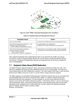
Intel® Server Board S2600GZ/GL TPS Platform Management Functional Overview methods, for the purpose of sending to an Intel engineer for an enhanced debugging capability. The files are compressed, encrypted, and password protected. The file is not meant to be viewable by the end user but rather to provide additional debugging capability to an Intel support engineer. A list of data that may be captured using this feature includes but is not limited to: Platform sensor readings - This includes all "readable" sensors that can be accessed by the BMC FW and have associated SDRs populated in the SDR repository. This does not include any "event-only" sensors. (All BIOS sensors and some BMC and ME sensors are "event-only"; meaning that they are not readable using an IPMI Get Sensor Reading command but rather are used just for event logging purposes). SEL - The current SEL contents are saved in both hexadecimal and text format. CPU/memory register data - useful for diagnosing the cause of the following system errors: CATERR, ERR[2], SMI timeout, PERR, and SERR. The debug data is saved and timestamped for the last 3 occurrences of the error conditions. o PCI error registers o MSR registers o MCH registers BMC configuration data o BMC FW debug log (that is, SysLog) - Captures FW debug messages. o Non-volatile storage of captured data. Some of the captured data will be stored persistently in the BMC's non-volatile flash memory and preserved across AC power cycles. Due to size limitations of the BMC's flash memory, it is not feasible to store all of the data persistently. SMBIOS table data. The entire SMBIOS table is captured from the last boot. PCI configuration data for on-board devices and add-in cards. The first 256 bytes of PCI configuration data is captured for each device for each boot. System memory map. The system memory map is provided by BIOS on the current boot. This includes the EFI memory map and the Legacy (E820) memory map depending on the current boot. Power supplies debug capability. o Capture of power supply "black box" data and power supply asset information. Power supply vendors are adding the capability to store debug data within the power supply itself. The platform debug feature provides a means to capture this data for each installed power supply. The data can be analyzed by Intel for failure analysis and possibly provided to the power supply vendor as well. The BMC gets this data from the power supplies from PMBus* manufacturer-specific commands. o Storage of system identification in power supply. The BMC copies board and system serial numbers and part numbers into the power supply whenever a new power supply is installed in the system or when the system is first powered on. This information is included as part of the power supply black box data for each installed power supply. Accessibility from IPMI interfaces. The platform debug file can be accessed from an external IPMI interface (KCS or LAN). POST code sequence for the two most recent boots. This is a best-effort data collection by the BMC as the BMC real-time response cannot guarantee that all POST codes are captured. Revision 1.1 73 Intel order number G24881-004
-
 1
1 -
2
-
3
-
4
-
5
-
6
-
7
-
8
-
9
-
10
-
11
-
12
-
13
-
14
-
15
-
16
-
17
-
18
-
19
-
20
-
21
-
22
-
23
-
24
-
25
-
26
-
27
-
28
-
29
-
30
-
31
-
32
-
33
-
34
-
35
-
36
-
37
-
38
-
39
-
40
-
41
-
42
-
43
-
44
-
45
-
46
-
47
-
48
-
49
-
50
-
51
-
52
-
53
-
54
-
55
-
56
-
57
-
58
-
59
-
60
-
61
-
62
-
63
-
64
-
65
-
66
-
67
-
68
-
69
-
70
-
71
-
72
-
73
-
74
-
75
-
76
-
77
-
78
-
79
-
80
-
 81
81 -
 82
82 -
 83
83 -
 84
84 -
 85
85 -
 86
86 -
 87
87 -
 88
88 -
 89
89 -
 90
90 -
 91
91 -
92
-
93
-
94
-
95
-
96
-
97
-
98
-
99
-
100
-
101
-
102
-
103
-
104
-
105
-
106
-
107
-
108
-
109
-
110
-
111
-
112
-
113
-
114
-
115
-
116
-
117
-
118
-
119
-
120
-
121
-
122
-
123
-
124
-
125
-
126
-
127
-
128
-
129
-
130
-
131
-
132
-
133
-
134
-
135
-
136
-
137
-
138
-
139
-
140
-
141
-
142
-
143
-
144
-
145
-
146
-
147
-
148
-
149
-
150
-
151
-
152
-
153
-
154
-
155
-
156
-
157
-
158
-
159
-
160
-
161
-
162
-
163
-
164
-
165
-
166
-
167
-
168
-
169
-
170
-
171
-
172
-
173
-
174
-
175
-
176
-
177
-
178
-
179
-
180
-
181
-
182
-
183
-
184
-
185
-
186
-
187
-
188
-
189
-
190
-
191
-
192
-
193
-
194
-
195
-
196
-
197
-
198
-
199
-
200
-
201
-
202
-
203
-
204
-
205
-
206
-
207
-
208
-
209
-
210
-
211
-
212
-
213
-
214
-
215
-
216
-
217
-
218
-
219
-
220
-
221
-
222
-
223
-
224
-
225
-
226
-
227
-
228
-
229
-
230
-
231
-
232
-
233
-
234
-
235
-
236
-
237
-
238
-
239
-
240
-
241
-
242
-
243
-
244
-
245
-
246
-
247
-
248
-
249
-
250
-
251
-
252
-
253
-
254
-
255
-
256
-
257
-
258
-
259
-
260
-
261
-
262
-
263
-
264
 |
 |
