Intel S2600GZ S2600GZ/GL - Page 112
System ID LED, System Status LED
 |
View all Intel S2600GZ manuals
Add to My Manuals
Save this manual to your list of manuals |
Page 112 highlights
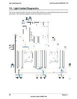
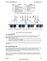
Intel® Server Board S2600GZ/GL TPS Light Guided Diagnostics Label A B C D E F G H Description System ID System Status POST Code Diagnostics 12V Stand-by Power Present CPU-2 Fault System Fan #6 Fan Fault System Fan #5 Fan Fault System Fan #4 Fan Fault Label I J K L M N O Description System Fan #3 Fan Fault Memory Fault System Fan #2 Fan Fault System Fan #1 Fan Fault CPU-1 Fault CATERR System Power Good Figure 37. On-Board Diagnostic LED Placement Figure 38. Memory Slot Fault LED Locations 10.1 System ID LED The server board includes a blue system ID LED which is used to visually identify a specific server installed among many other similar servers. There are two options available for illuminating the System ID LED. 1. The front panel ID LED Button is pushed, which causes the LED to illuminate to a solid on state until the button is pushed again. 2. An IPMI "Chassis Identify" command is remotely entered, which causes the LED to blink The System ID LED on the server board is tied directly to the System ID LED on system front panel if present. 10.2 System Status LED The server board includes a bi-color System Status LED. The System Status LED on the server board is tied directly to the System Status LED on the front panel (if present). This LED indicates the current health of the server. Possible LED states include solid green, blinking green, blinking amber, and solid amber. When the server is powered down (transitions to the DC-off state or S5), the BMC is still on standby power and retains the sensor and front panel status LED state established before the power-down event. Revision 1.1 99 Intel order number G24881-004
-
 1
1 -
2
-
3
-
4
-
5
-
6
-
7
-
8
-
9
-
10
-
11
-
12
-
13
-
14
-
15
-
16
-
17
-
18
-
19
-
20
-
21
-
22
-
23
-
24
-
25
-
26
-
27
-
28
-
29
-
30
-
31
-
32
-
33
-
34
-
35
-
36
-
37
-
38
-
39
-
40
-
41
-
42
-
43
-
44
-
45
-
46
-
47
-
48
-
49
-
50
-
51
-
52
-
53
-
54
-
55
-
56
-
57
-
58
-
59
-
60
-
61
-
62
-
63
-
64
-
65
-
66
-
67
-
68
-
69
-
70
-
71
-
72
-
73
-
74
-
75
-
76
-
77
-
78
-
79
-
80
-
81
-
82
-
83
-
84
-
85
-
86
-
87
-
88
-
89
-
90
-
91
-
92
-
93
-
94
-
95
-
96
-
97
-
98
-
99
-
100
-
101
-
102
-
103
-
104
-
105
-
106
-
 107
107 -
 108
108 -
 109
109 -
 110
110 -
 111
111 -
 112
112 -
 113
113 -
 114
114 -
 115
115 -
 116
116 -
 117
117 -
118
-
119
-
120
-
121
-
122
-
123
-
124
-
125
-
126
-
127
-
128
-
129
-
130
-
131
-
132
-
133
-
134
-
135
-
136
-
137
-
138
-
139
-
140
-
141
-
142
-
143
-
144
-
145
-
146
-
147
-
148
-
149
-
150
-
151
-
152
-
153
-
154
-
155
-
156
-
157
-
158
-
159
-
160
-
161
-
162
-
163
-
164
-
165
-
166
-
167
-
168
-
169
-
170
-
171
-
172
-
173
-
174
-
175
-
176
-
177
-
178
-
179
-
180
-
181
-
182
-
183
-
184
-
185
-
186
-
187
-
188
-
189
-
190
-
191
-
192
-
193
-
194
-
195
-
196
-
197
-
198
-
199
-
200
-
201
-
202
-
203
-
204
-
205
-
206
-
207
-
208
-
209
-
210
-
211
-
212
-
213
-
214
-
215
-
216
-
217
-
218
-
219
-
220
-
221
-
222
-
223
-
224
-
225
-
226
-
227
-
228
-
229
-
230
-
231
-
232
-
233
-
234
-
235
-
236
-
237
-
238
-
239
-
240
-
241
-
242
-
243
-
244
-
245
-
246
-
247
-
248
-
249
-
250
-
251
-
252
-
253
-
254
-
255
-
256
-
257
-
258
-
259
-
260
-
261
-
262
-
263
-
264
 |
 |
