Intel S2600GZ S2600GZ/GL - Page 227
Appendix A: Integration and Usage Tips
 |
View all Intel S2600GZ manuals
Add to My Manuals
Save this manual to your list of manuals |
Page 227 highlights
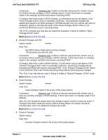
Appendix A: Integration and Usage Tips Intel® Server Board S2600GZ/GL TPS Appendix A: Integration and Usage Tips When adding or removing components or peripherals from the server board, power cords must be disconnected from the server. With power applied to the server, standby voltages are still present even though the server board is powered off. This server board supports the Intel® Xeon® Processor E5-2600 product family with a Thermal Design Power (TDP) of up to and including 135 Watts. Previous generations of the Intel® Xeon® processors are not supported. Server systems using this server board may or may not meet the TDP design limits of the server board. Validate the TDP limits of the server system before selecting a processor. Processors must be installed in order. CPU 1 must be populated for the server board to operate. Riser card slot #2 is only functional with two CPUs installed. The SCU-1 mini-SAS connector is only enabled when an 8-port Intel® RAID C600 Upgrade Key is installed. This server board only supports registered DDR3 DIMMs (RDIMMs) and unbuffered DDR3 DIMMs (UDIMMs). Mixing of RDIMMs and UDIMMs is not supported. For the best performance, the number of DDR3 DIMMs installed should be balanced across both processor sockets and memory channels. On the back edge of the server board are eight diagnostic LEDs that display a sequence of amber POST codes during the boot process. If the server board hangs during POST, the LEDs display the last POST event run before the hang. The Intel® Remote Management Module 4 (Intel® RMM4) connector is not compatible with any previous versions of the Intel® Remote Management Module (Product Order Code - AXXRMM, AXXRMM2, AXXRMM3). 214 Revision 1.1 Intel order number G24881-004
-
 1
1 -
2
-
3
-
4
-
5
-
6
-
7
-
8
-
9
-
10
-
11
-
12
-
13
-
14
-
15
-
16
-
17
-
18
-
19
-
20
-
21
-
22
-
23
-
24
-
25
-
26
-
27
-
28
-
29
-
30
-
31
-
32
-
33
-
34
-
35
-
36
-
37
-
38
-
39
-
40
-
41
-
42
-
43
-
44
-
45
-
46
-
47
-
48
-
49
-
50
-
51
-
52
-
53
-
54
-
55
-
56
-
57
-
58
-
59
-
60
-
61
-
62
-
63
-
64
-
65
-
66
-
67
-
68
-
69
-
70
-
71
-
72
-
73
-
74
-
75
-
76
-
77
-
78
-
79
-
80
-
81
-
82
-
83
-
84
-
85
-
86
-
87
-
88
-
89
-
90
-
91
-
92
-
93
-
94
-
95
-
96
-
97
-
98
-
99
-
100
-
101
-
102
-
103
-
104
-
105
-
106
-
107
-
108
-
109
-
110
-
111
-
112
-
113
-
114
-
115
-
116
-
117
-
118
-
119
-
120
-
121
-
122
-
123
-
124
-
125
-
126
-
127
-
128
-
129
-
130
-
131
-
132
-
133
-
134
-
135
-
136
-
137
-
138
-
139
-
140
-
141
-
142
-
143
-
144
-
145
-
146
-
147
-
148
-
149
-
150
-
151
-
152
-
153
-
154
-
155
-
156
-
157
-
158
-
159
-
160
-
161
-
162
-
163
-
164
-
165
-
166
-
167
-
168
-
169
-
170
-
171
-
172
-
173
-
174
-
175
-
176
-
177
-
178
-
179
-
180
-
181
-
182
-
183
-
184
-
185
-
186
-
187
-
188
-
189
-
190
-
191
-
192
-
193
-
194
-
195
-
196
-
197
-
198
-
199
-
200
-
201
-
202
-
203
-
204
-
205
-
206
-
207
-
208
-
209
-
210
-
211
-
212
-
213
-
214
-
215
-
216
-
217
-
218
-
219
-
220
-
221
-
 222
222 -
 223
223 -
 224
224 -
 225
225 -
 226
226 -
 227
227 -
 228
228 -
 229
229 -
 230
230 -
 231
231 -
 232
232 -
233
-
234
-
235
-
236
-
237
-
238
-
239
-
240
-
241
-
242
-
243
-
244
-
245
-
246
-
247
-
248
-
249
-
250
-
251
-
252
-
253
-
254
-
255
-
256
-
257
-
258
-
259
-
260
-
261
-
262
-
263
-
264
 |
 |
