Intel S2600GZ S2600GZ/GL - Page 97
Power/Sleep Button and LED Support, 2.1.2, System ID Button and LED Support, 2.1.3, System
 |
View all Intel S2600GZ manuals
Add to My Manuals
Save this manual to your list of manuals |
Page 97 highlights
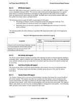
On-board Connector/Header Overview Intel® Server Board S2600GZ/GL TPS On the server board, this header is labeled "FRONT PANEL". The following table provides the pin-out for this header. Table 28. SSI Front Panel Header Pin-out ("Front Panel") Signal Description Pin# Pin# Signal Description P3V3_AUX 1 2 P3V3_AUX KEY 4 P5V_STBY FP_PWR_LED_BUF_R_N 5 6 FP_ID_LED_BUF_R_N P3V3 7 8 FP_LED_STATUS_GREEN_R_N LED_HDD_ACTIVITY_R_N 9 10 FP_LED_STATUS_AMBER_R_N FP_PWR_BTN_N 11 12 LED _NIC_LINK0_ACT_FP_N GROUND 13 14 LED _NIC_LINK0_LNKUP_FP_N FP_RST_BTN_R_N 15 16 SMB_SENSOR_3V3STBY_DATA_R0 GROUND 17 18 SMB_SENSOR_3V3STBY_CLK FP_ID_BTN_R_N 19 20 FP_CHASSIS_INTRUSION PU_FM_SIO_TEMP_SENSOR 21 22 LED_NIC_LINK1_ACT_FP_N FP_NMI_BTN_R_N 23 24 LED_NIC_LINK1_LNKUP_FP_N KEY KEY LED_NIC_LINK2_ACT_FP_N 27 28 LED_NIC_LINK3_ACT_FP_N LED_NIC_LINK2_LNKUP_FP_N 29 30 LED_NIC_LINK3_LNKUP_FP_N 8.2.1.1 Power/Sleep Button and LED Support Pressing the Power button will toggle the system power on and off. This button also functions as a sleep button if enabled by an ACPI compliant operating system. Pressing this button will send a signal to the integrated BMC, which will power on or power off the system. The power LED is a single color and is capable of supporting different indicator states as defined in the following table. Table 29. Power/Sleep LED Functional States State Power-off Power-on S5 S4 S3-S1 S0 Power Mode Non-ACPI Non-ACPI ACPI ACPI ACPI ACPI LED Off On Off Off Slow blink1 Steady on Description System power is off, and the BIOS has not initialized the chipset. System power is on Mechanical is off, and the operating system has not saved any context to the hard disk. Mechanical is off. The operating system has saved context to the hard disk. DC power is still on. The operating system has saved context and gone into a level of low-power state. System and the operating system are up and running. 8.2.1.2 System ID Button and LED Support Pressing the System ID Button will toggle both the ID LED on the front panel and the Blue ID LED on the server board on and off. The System ID LED is used to identify the system for maintenance when installed in a rack of similar server systems. The System ID LED can also be toggled on and off remotely using the IPMI "Chassis Identify" command which will cause the LED to blink for 15 seconds. 8.2.1.3 System Reset Button Support When pressed, this button will reboot and re-initialize the system 84 Revision 1.1 Intel order number G24881-004
-
 1
1 -
2
-
3
-
4
-
5
-
6
-
7
-
8
-
9
-
10
-
11
-
12
-
13
-
14
-
15
-
16
-
17
-
18
-
19
-
20
-
21
-
22
-
23
-
24
-
25
-
26
-
27
-
28
-
29
-
30
-
31
-
32
-
33
-
34
-
35
-
36
-
37
-
38
-
39
-
40
-
41
-
42
-
43
-
44
-
45
-
46
-
47
-
48
-
49
-
50
-
51
-
52
-
53
-
54
-
55
-
56
-
57
-
58
-
59
-
60
-
61
-
62
-
63
-
64
-
65
-
66
-
67
-
68
-
69
-
70
-
71
-
72
-
73
-
74
-
75
-
76
-
77
-
78
-
79
-
80
-
81
-
82
-
83
-
84
-
85
-
86
-
87
-
88
-
89
-
90
-
91
-
 92
92 -
 93
93 -
 94
94 -
 95
95 -
 96
96 -
 97
97 -
 98
98 -
 99
99 -
 100
100 -
 101
101 -
 102
102 -
103
-
104
-
105
-
106
-
107
-
108
-
109
-
110
-
111
-
112
-
113
-
114
-
115
-
116
-
117
-
118
-
119
-
120
-
121
-
122
-
123
-
124
-
125
-
126
-
127
-
128
-
129
-
130
-
131
-
132
-
133
-
134
-
135
-
136
-
137
-
138
-
139
-
140
-
141
-
142
-
143
-
144
-
145
-
146
-
147
-
148
-
149
-
150
-
151
-
152
-
153
-
154
-
155
-
156
-
157
-
158
-
159
-
160
-
161
-
162
-
163
-
164
-
165
-
166
-
167
-
168
-
169
-
170
-
171
-
172
-
173
-
174
-
175
-
176
-
177
-
178
-
179
-
180
-
181
-
182
-
183
-
184
-
185
-
186
-
187
-
188
-
189
-
190
-
191
-
192
-
193
-
194
-
195
-
196
-
197
-
198
-
199
-
200
-
201
-
202
-
203
-
204
-
205
-
206
-
207
-
208
-
209
-
210
-
211
-
212
-
213
-
214
-
215
-
216
-
217
-
218
-
219
-
220
-
221
-
222
-
223
-
224
-
225
-
226
-
227
-
228
-
229
-
230
-
231
-
232
-
233
-
234
-
235
-
236
-
237
-
238
-
239
-
240
-
241
-
242
-
243
-
244
-
245
-
246
-
247
-
248
-
249
-
250
-
251
-
252
-
253
-
254
-
255
-
256
-
257
-
258
-
259
-
260
-
261
-
262
-
263
-
264
 |
 |
