Intel S2600GZ S2600GZ/GL - Page 247
POST Memory Initialization MRC Diagnostic Codes
 |
View all Intel S2600GZ manuals
Add to My Manuals
Save this manual to your list of manuals |
Page 247 highlights
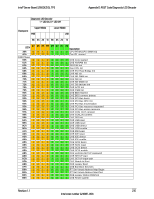
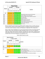
Appendix D: POST Code Diagnostic LED Decoder Intel® Server Board S2600GZ/GL TPS Diagnostic LED Decoder 1 = LED On, 0 = LED Off Checkpoint Upper Nibble MSB Lower Nibble LSB 8h 4h 2h 1h 8h 4h 2h 1h LED # #7 #6 #5 #4 #3 #2 #1 #0 Description B4h 1 0 1 1 0 1 0 0 DXE USB Hot plug B5h 1 0 1 1 0 1 0 1 DXE PCI BUS Hot plug B6h 1 0 1 1 0 1 1 0 DXE NVRAM cleanup B7h 1 0 1 1 0 1 1 1 DXE Configuration Reset 00h 0 0 0 0 0 0 0 0 INT19 S3 Resume E0h 1 1 0 1 0 0 0 0 S3 Resume PEIM (S3 started) E1h 1 1 0 1 0 0 0 1 S3 Resume PEIM (S3 boot script) E2h 1 1 0 1 0 0 1 0 S3 Resume PEIM (S3 Video Repost) E3h 1 1 0 1 0 0 1 1 S3 Resume PEIM (S3 OS wake) BIOS Recovery F0h 1 1 1 1 0 0 0 0 PEIM which detected forced Recovery condition F1h 1 1 1 1 0 0 0 1 PEIM which detected User Recovery condition F2h 1 1 1 1 0 0 1 0 Recovery PEIM (Recovery started) F3h 1 1 1 1 0 0 1 1 Recovery PEIM (Capsule found) F4h 1 1 1 1 0 1 0 0 Recovery PEIM (Capsule loaded) POST Memory Initialization MRC Diagnostic Codes There are two types of POST Diagnostic Codes displayed by the MRC during memory initialization; Progress Codes and Fatal Error Codes. The MRC Progress Codes are displays to the Diagnostic LEDs that show the execution point in the MRC operational path at each step. Table 60. MRC Progress Codes Diagnostic LED Decoder 1 = LED On, 0 = LED Off Upper Nibble Lower Nibble Checkpoint MSB LSB 8h 4h 2h 1h 8h 4h 2h 1h Description LED #7 #6 #5 #4 #3 #2 #1 #0 MRC Progress Codes B0h 1 0 1 1 0 0 0 0 Detect DIMM population B1h 1 0 1 1 0 0 0 1 Set DDR3 frequency B2h 1 0 1 1 0 0 1 0 Gather remaining SPD data B3h 1 0 1 1 0 0 1 1 Program registers on the memory controller level 234 Revision 1.1 Intel order number G24881-004
-
 1
1 -
2
-
3
-
4
-
5
-
6
-
7
-
8
-
9
-
10
-
11
-
12
-
13
-
14
-
15
-
16
-
17
-
18
-
19
-
20
-
21
-
22
-
23
-
24
-
25
-
26
-
27
-
28
-
29
-
30
-
31
-
32
-
33
-
34
-
35
-
36
-
37
-
38
-
39
-
40
-
41
-
42
-
43
-
44
-
45
-
46
-
47
-
48
-
49
-
50
-
51
-
52
-
53
-
54
-
55
-
56
-
57
-
58
-
59
-
60
-
61
-
62
-
63
-
64
-
65
-
66
-
67
-
68
-
69
-
70
-
71
-
72
-
73
-
74
-
75
-
76
-
77
-
78
-
79
-
80
-
81
-
82
-
83
-
84
-
85
-
86
-
87
-
88
-
89
-
90
-
91
-
92
-
93
-
94
-
95
-
96
-
97
-
98
-
99
-
100
-
101
-
102
-
103
-
104
-
105
-
106
-
107
-
108
-
109
-
110
-
111
-
112
-
113
-
114
-
115
-
116
-
117
-
118
-
119
-
120
-
121
-
122
-
123
-
124
-
125
-
126
-
127
-
128
-
129
-
130
-
131
-
132
-
133
-
134
-
135
-
136
-
137
-
138
-
139
-
140
-
141
-
142
-
143
-
144
-
145
-
146
-
147
-
148
-
149
-
150
-
151
-
152
-
153
-
154
-
155
-
156
-
157
-
158
-
159
-
160
-
161
-
162
-
163
-
164
-
165
-
166
-
167
-
168
-
169
-
170
-
171
-
172
-
173
-
174
-
175
-
176
-
177
-
178
-
179
-
180
-
181
-
182
-
183
-
184
-
185
-
186
-
187
-
188
-
189
-
190
-
191
-
192
-
193
-
194
-
195
-
196
-
197
-
198
-
199
-
200
-
201
-
202
-
203
-
204
-
205
-
206
-
207
-
208
-
209
-
210
-
211
-
212
-
213
-
214
-
215
-
216
-
217
-
218
-
219
-
220
-
221
-
222
-
223
-
224
-
225
-
226
-
227
-
228
-
229
-
230
-
231
-
232
-
233
-
234
-
235
-
236
-
237
-
238
-
239
-
240
-
241
-
 242
242 -
 243
243 -
 244
244 -
 245
245 -
 246
246 -
 247
247 -
 248
248 -
 249
249 -
 250
250 -
 251
251 -
 252
252 -
253
-
254
-
255
-
256
-
257
-
258
-
259
-
260
-
261
-
262
-
263
-
264
 |
 |
