Intel S2600GZ S2600GZ/GL - Page 116
Power Supply Specification Guidelines
 |
View all Intel S2600GZ manuals
Add to My Manuals
Save this manual to your list of manuals |
Page 116 highlights
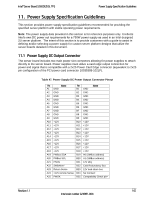
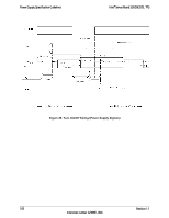
Intel® Server Board S2600GZ/GL TPS Power Supply Specification Guidelines 11. Power Supply Specification Guidelines This section provides power supply specification guidelines recommended for providing the specified server platform with stable operating power requirements. Note: The power supply data provided in this section is for reference purposes only. It reflects Intel's own DC power out requirements for a 750W power supply as used in an Intel designed 2U server platform. The intent of this section is to provide customers with a guide to assist in defining and/or selecting a power supply for custom server platform designs that utilize the server boards detailed in this document. 11.1 Power Supply DC Output Connector The server board includes two main power slot connectors allowing for power supplies to attach directly to the server board. Power supplies must utilize a card edge output connection for power and signal that is compatible with a 2x25 Power Card Edge connector (equivalent to 2x25 pin configuration of the FCI power card connector 10035388-102LF). Table 47. Power Supply DC Power Output Connector Pinout Pin Name A1 GND Pin B1 GND Name A2 GND B2 GND A3 GND B3 GND A4 GND B4 GND A5 GND B5 GND A6 GND B6 GND A7 GND B7 GND A8 GND B8 GND A9 GND B9 GND A10 +12V B10 +12V A11 +12V B11 +12V A12 +12V B12 +12V A13 +12V B13 +12V A14 +12V B14 +12V A15 +12V B15 +12V A16 +12V B16 +12V A17 +12V B17 +12V A18 +12V B18 +12V A19 PMBus SDA B19 A0 (SMBus address) A20 PMBus SCL B20 A1 (SMBus address) A21 PSON B21 12V stby A22 SMBAlert# B22 Cold Redundancy Bus A23 Return Sense B23 12V load share bus A24 +12V remote Sense B24 No Connect A25 PWOK B25 Compatibility Check pin* Revision 1.1 103 Intel order number G24881-004
-
 1
1 -
2
-
3
-
4
-
5
-
6
-
7
-
8
-
9
-
10
-
11
-
12
-
13
-
14
-
15
-
16
-
17
-
18
-
19
-
20
-
21
-
22
-
23
-
24
-
25
-
26
-
27
-
28
-
29
-
30
-
31
-
32
-
33
-
34
-
35
-
36
-
37
-
38
-
39
-
40
-
41
-
42
-
43
-
44
-
45
-
46
-
47
-
48
-
49
-
50
-
51
-
52
-
53
-
54
-
55
-
56
-
57
-
58
-
59
-
60
-
61
-
62
-
63
-
64
-
65
-
66
-
67
-
68
-
69
-
70
-
71
-
72
-
73
-
74
-
75
-
76
-
77
-
78
-
79
-
80
-
81
-
82
-
83
-
84
-
85
-
86
-
87
-
88
-
89
-
90
-
91
-
92
-
93
-
94
-
95
-
96
-
97
-
98
-
99
-
100
-
101
-
102
-
103
-
104
-
105
-
106
-
107
-
108
-
109
-
110
-
 111
111 -
 112
112 -
 113
113 -
 114
114 -
 115
115 -
 116
116 -
 117
117 -
 118
118 -
 119
119 -
 120
120 -
 121
121 -
122
-
123
-
124
-
125
-
126
-
127
-
128
-
129
-
130
-
131
-
132
-
133
-
134
-
135
-
136
-
137
-
138
-
139
-
140
-
141
-
142
-
143
-
144
-
145
-
146
-
147
-
148
-
149
-
150
-
151
-
152
-
153
-
154
-
155
-
156
-
157
-
158
-
159
-
160
-
161
-
162
-
163
-
164
-
165
-
166
-
167
-
168
-
169
-
170
-
171
-
172
-
173
-
174
-
175
-
176
-
177
-
178
-
179
-
180
-
181
-
182
-
183
-
184
-
185
-
186
-
187
-
188
-
189
-
190
-
191
-
192
-
193
-
194
-
195
-
196
-
197
-
198
-
199
-
200
-
201
-
202
-
203
-
204
-
205
-
206
-
207
-
208
-
209
-
210
-
211
-
212
-
213
-
214
-
215
-
216
-
217
-
218
-
219
-
220
-
221
-
222
-
223
-
224
-
225
-
226
-
227
-
228
-
229
-
230
-
231
-
232
-
233
-
234
-
235
-
236
-
237
-
238
-
239
-
240
-
241
-
242
-
243
-
244
-
245
-
246
-
247
-
248
-
249
-
250
-
251
-
252
-
253
-
254
-
255
-
256
-
257
-
258
-
259
-
260
-
261
-
262
-
263
-
264
 |
 |