Intel S2600GZ S2600GZ/GL - Page 115
Post Code Diagnostic LEDs, Volt Stand-By Present LED, Fan Fault LEDs, Memory Fault LEDs, CPU Fault
 |
View all Intel S2600GZ manuals
Add to My Manuals
Save this manual to your list of manuals |
Page 115 highlights
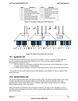
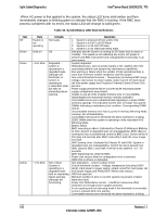
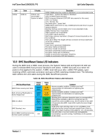
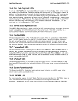
Light Guided Diagnostics Intel® Server Board S2600GZ/GL TPS 10.4 Post Code Diagnostic LEDs A bank of eight POST code diagnostic LEDs are located on the back edge of the server next to the stacked USB connectors. During the system boot process, the BIOS executes a number of platform configuration processes, each of which is assigned a specific hex POST code number. As each configuration routine is started, the BIOS displays the given POST code to the POST code diagnostic LEDs. The purpose of these LEDs is to assist in troubleshooting a system hang condition during the POST process. The diagnostic LEDs can be used to identify the last POST process to be executed. See Appendix D for a complete description of how these LEDs are read, and for a list of all supported POST codes 10.5 12 Volt Stand-By Present LED This LED is illuminated when a power cord (AC or DC) is connected to the server and the power supply is supplying 12 Volt Stand-by power to the server board. This LED is intended as a service caution indicator to anyone accessing the inside of the server system. 10.6 Fan Fault LEDs The server board includes a Fan Fault LED next to each of the six system fans and both CPU fans. The LED has two states: On and Off. The BMC lights a fan fault LED if the associated fan-tach sensor has a lower critical threshold event status asserted. Fan-tach sensors are manual re-arm sensors. Once the lower critical threshold is crossed, the LED remains lit until the sensor is rearmed. These sensors are rearmed at system DC power-on and system reset. 10.7 Memory Fault LEDs The server board includes a Memory Fault LED for each DIMM slot. When the BIOS detects a memory fault condition, it sends an IPMI OEM command (Set Fault Indication) to the BMC to instruct the BMC to turn on the associated Memory Slot Fault LED. These LEDs are only active when the system is in the 'on' state. The BMC will not activate or change the state of the LEDs unless instructed by the BIOS. 10.8 CPU Fault LEDs The server board includes a CPU fault LED for each CPU socket. The CPU Fault LED is lit if there is an MSID mismatch error is detected (that is, CPU power rating is incompatible with the board). 10.9 System Power Good LED The Power Good LED is illuminated when system power is turned on and DC power to the server board is within acceptable limits. 10.10 CATERR LED For processors that support the Intel® Quick Path Interconnect interface, the CATERR# signal is used to indicate that a catastrophic error condition has been experienced by the processor. Should such an error occur, the CATERR LED on the server board will illuminate. 102 Revision 1.1 Intel order number G24881-004
-
 1
1 -
2
-
3
-
4
-
5
-
6
-
7
-
8
-
9
-
10
-
11
-
12
-
13
-
14
-
15
-
16
-
17
-
18
-
19
-
20
-
21
-
22
-
23
-
24
-
25
-
26
-
27
-
28
-
29
-
30
-
31
-
32
-
33
-
34
-
35
-
36
-
37
-
38
-
39
-
40
-
41
-
42
-
43
-
44
-
45
-
46
-
47
-
48
-
49
-
50
-
51
-
52
-
53
-
54
-
55
-
56
-
57
-
58
-
59
-
60
-
61
-
62
-
63
-
64
-
65
-
66
-
67
-
68
-
69
-
70
-
71
-
72
-
73
-
74
-
75
-
76
-
77
-
78
-
79
-
80
-
81
-
82
-
83
-
84
-
85
-
86
-
87
-
88
-
89
-
90
-
91
-
92
-
93
-
94
-
95
-
96
-
97
-
98
-
99
-
100
-
101
-
102
-
103
-
104
-
105
-
106
-
107
-
108
-
109
-
 110
110 -
 111
111 -
 112
112 -
 113
113 -
 114
114 -
 115
115 -
 116
116 -
 117
117 -
 118
118 -
 119
119 -
 120
120 -
121
-
122
-
123
-
124
-
125
-
126
-
127
-
128
-
129
-
130
-
131
-
132
-
133
-
134
-
135
-
136
-
137
-
138
-
139
-
140
-
141
-
142
-
143
-
144
-
145
-
146
-
147
-
148
-
149
-
150
-
151
-
152
-
153
-
154
-
155
-
156
-
157
-
158
-
159
-
160
-
161
-
162
-
163
-
164
-
165
-
166
-
167
-
168
-
169
-
170
-
171
-
172
-
173
-
174
-
175
-
176
-
177
-
178
-
179
-
180
-
181
-
182
-
183
-
184
-
185
-
186
-
187
-
188
-
189
-
190
-
191
-
192
-
193
-
194
-
195
-
196
-
197
-
198
-
199
-
200
-
201
-
202
-
203
-
204
-
205
-
206
-
207
-
208
-
209
-
210
-
211
-
212
-
213
-
214
-
215
-
216
-
217
-
218
-
219
-
220
-
221
-
222
-
223
-
224
-
225
-
226
-
227
-
228
-
229
-
230
-
231
-
232
-
233
-
234
-
235
-
236
-
237
-
238
-
239
-
240
-
241
-
242
-
243
-
244
-
245
-
246
-
247
-
248
-
249
-
250
-
251
-
252
-
253
-
254
-
255
-
256
-
257
-
258
-
259
-
260
-
261
-
262
-
263
-
264
 |
 |
