Brother International LZ2-B856E Instruction Manual - English and Spanish - Page 98
Setting the zigzag base line position
 |
View all Brother International LZ2-B856E manuals
Add to My Manuals
Save this manual to your list of manuals |
Page 98 highlights
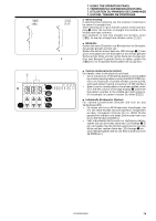
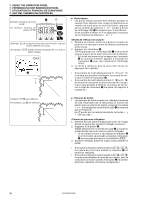
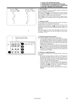
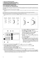
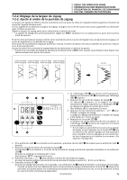
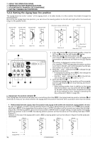
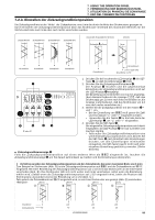
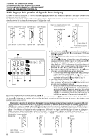
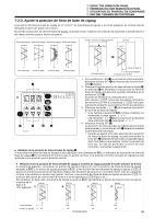
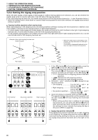
7. USING THE OPERATION PANEL 7. VERWENDUNG DER BEDIENUNGSTAFEL 7. UTILISATION DU PANNEAU DE COMMANDE 7. USO DEL TABLERO DE CONTROLES 7-2-3. Setting the zigzag base line position The zigzag base line is the "center" of the zigzag stitch, or in other words, it is like a center line drawn through the sewing pattern. By moving the zigzag base line position, you can move the sewing pattern to the left and right within the maximum range for the pattern width. Zigzag width Zigzag width Zigzag width Zigzag width Maximum zigzag width (8 mm) Zigzag width 3mm (8 mm) 3mm Base line Base line Base line Base line Base line 0 Base line 0 2 mm to the left Base line L20 q TEST SET 12 3 4 56 7 8 9 PAT T ERN S S ROM L r w t L or r re 1. If the LED display q is illuminated steadily, press the SET key w so that the LED display q flashes. 2. Press the zigzag base line position key e. The indicator r will illuminate, and the zigzag base line position currently set will flash on the LED display q. The setting is displayed in units of 0.1 mm. (For example, L20 indicates that the pattern position is 2.0 mm to the left, and r20 indicates that the pat- tern position is 2.0 mm to the right.) 3. Press the ˚ and ˜ selection keys t to change the zig- zag base line position. • If changing the setting from ++0, first change the numerals, and then set "L" or "r". • Use the ˚ and ˜ selection keys t for the left col- umn of the LED display q to set "L" or "r". 4. Press the SET key w. The selected zigzag base line position will be accepted, and the LED display q will stop flashing and illuminate steadily. * When setting another item in addition to the zigzag base line position, you can press the SET key w after all other settings have been completed to accept all of the settings at once, instead of pressing the key at this point. (Refer to page 66.) ˙ Zigzag base line position indicator r If the zigzag base line position has been set to something other than ++0, the zigzag base line position indicator r will illuminate so that you can check whether the zigzag base line position has been set to a position other than the center. ˔ Relationship between zigzag base line position and zigzag width (when the maximum zigzag width is 8 mm) By way of example, consider a sewing pattern (Figure A) with a zigzag base line position set to ++0 and a zigzag width set to +40. If the zigzag base line position is set to L20, the pattern will be moved over toward the left edge (Figure B). The sewing pattern cannot move any further to the left even if a larger setting is made. (Even if the zigzag base line position is set to L30, the sewing pattern position will be the same as if the setting had been L20 (Figure C.) However, in this case, if the zigzag width is set to +20, a sewing pattern such as that shown in Figure D will be produced. (8mm) (8mm) (8mm) (8mm) A 4mm B 4mm C 4mm D 2mm Base line -------- 0 Zigzag width -------- 40 79 L20 L30 L30 40 40 20 LZ2-B855E,B856E
-
 1
1 -
2
-
3
-
4
-
5
-
6
-
7
-
8
-
9
-
10
-
11
-
12
-
13
-
14
-
15
-
16
-
17
-
18
-
19
-
20
-
21
-
22
-
23
-
24
-
25
-
26
-
27
-
28
-
29
-
30
-
31
-
32
-
33
-
34
-
35
-
36
-
37
-
38
-
39
-
40
-
41
-
42
-
43
-
44
-
45
-
46
-
47
-
48
-
49
-
50
-
51
-
52
-
53
-
54
-
55
-
56
-
57
-
58
-
59
-
60
-
61
-
62
-
63
-
64
-
65
-
66
-
67
-
68
-
69
-
70
-
71
-
72
-
73
-
74
-
75
-
76
-
77
-
78
-
79
-
80
-
81
-
82
-
83
-
84
-
85
-
86
-
87
-
88
-
89
-
90
-
91
-
92
-
 93
93 -
 94
94 -
 95
95 -
 96
96 -
 97
97 -
 98
98 -
 99
99 -
 100
100 -
 101
101 -
 102
102 -
 103
103 -
104
-
105
-
106
-
107
-
108
-
109
-
110
-
111
-
112
-
113
-
114
-
115
-
116
-
117
-
118
-
119
-
120
-
121
-
122
-
123
-
124
-
125
-
126
-
127
-
128
-
129
-
130
-
131
-
132
-
133
-
134
-
135
-
136
-
137
-
138
-
139
-
140
-
141
-
142
-
143
-
144
-
145
-
146
-
147
-
148
-
149
-
150
-
151
-
152
-
153
-
154
-
155
-
156
-
157
-
158
-
159
-
160
-
161
-
162
-
163
-
164
-
165
-
166
-
167
-
168
-
169
-
170
-
171
-
172
-
173
-
174
-
175
-
176
-
177
-
178
-
179
-
180
-
181
-
182
-
183
-
184
-
185
-
186
-
187
-
188
-
189
-
190
-
191
-
192
-
193
-
194
-
195
-
196
-
197
-
198
-
199
-
200
-
201
-
202
-
203
-
204
-
205
-
206
-
207
-
208
-
209
-
210
-
211
-
212
-
213
-
214
-
215
-
216
-
217
-
218
-
219
-
220
-
221
-
222
 |
 |
