Dell PowerEdge XE2420 EMC Installation and Service Manual - Page 10
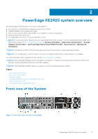
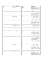
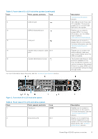
Table 1. Front view of 2 x 2.5-inch drive system, Ports, panels, and slots, Description, IOIOI
 |
View all Dell PowerEdge XE2420 manuals
Add to My Manuals
Save this manual to your list of manuals |
Page 10 highlights
Table 1. Front view of 2 x 2.5-inch drive system Item Ports, panels, and slots 1 Serial port Icon IOIOI 2 GPU riser 1 slots N/A 3 GPU riser 2 slots N/A 4 Drive slots N/A 5 Power supply unit (1) N/A 6 Power supply unit (2) N/A 7 iDRAC Direct port 8 Power button 9 OCP ports 10 Ethernet ports 10 PowerEdge XE2420 system overview Description Enables you to connect a serial device to the system. For more information, see the Technical specifications section. The GPU card slot (riser 1) connects up to two full-height GPUs. For more information, see the Expansion card installation guidelines section. The GPU card slot (riser 2) connects up to two full-height GPUs. For more information, see the Expansion card installation guidelines section. Enable you to install drives that are supported on your system. For more information about drives, see Technical specifications section. For more information, see Technical specifications section. For more information, see Technical specifications section. The iDRAC Direct port is micro USB 2.0-compliant. This port enables you to access the iDRAC Direct features. For more information, see the iDRAC User's Guide at www.dell.com/idracmanuals Indicates if the system is turned on or off. Press the power button to manually turn on or off the system. NOTE: Press the power button to gracefully shut down an ACPI-compliant operating system. The NIC ports that are integrated on the network daughter card (NDC) provide network connectivity. For more information about the supported configurations, see Technical specifications section. Use the Ethernet ports to connect Local Area Networks (LANs) to the system. For more information about the supported Ethernet ports, see
-
 1
1 -
2
-
3
-
4
-
 5
5 -
 6
6 -
 7
7 -
 8
8 -
 9
9 -
 10
10 -
 11
11 -
 12
12 -
 13
13 -
 14
14 -
 15
15 -
16
-
17
-
18
-
19
-
20
-
21
-
22
-
23
-
24
-
25
-
26
-
27
-
28
-
29
-
30
-
31
-
32
-
33
-
34
-
35
-
36
-
37
-
38
-
39
-
40
-
41
-
42
-
43
-
44
-
45
-
46
-
47
-
48
-
49
-
50
-
51
-
52
-
53
-
54
-
55
-
56
-
57
-
58
-
59
-
60
-
61
-
62
-
63
-
64
-
65
-
66
-
67
-
68
-
69
-
70
-
71
-
72
-
73
-
74
-
75
-
76
-
77
-
78
-
79
-
80
-
81
-
82
-
83
-
84
-
85
-
86
-
87
-
88
-
89
-
90
-
91
-
92
-
93
-
94
-
95
-
96
-
97
-
98
-
99
-
100
-
101
-
102
-
103
-
104
-
105
-
106
-
107
-
108
-
109
-
110
-
111
-
112
-
113
-
114
-
115
-
116
-
117
-
118
-
119
-
120
-
121
-
122
-
123
-
124
-
125
-
126
-
127
-
128
-
129
-
130
-
131
-
132
-
133
-
134
-
135
-
136
-
137
-
138
-
139
-
140
-
141
-
142
-
143
-
144
-
145
-
146
-
147
-
148
-
149
-
150
-
151
-
152
-
153
-
154
-
155
-
156
-
157
-
158
-
159
-
160
-
161
-
162
-
163
-
164
-
165
-
166
-
167
-
168
-
169
-
170
-
171
-
172
-
173
-
174
-
175
-
176
-
177
 |
 |
