Dell PowerEdge XE2420 EMC Installation and Service Manual - Page 108
Expansion cards and expansion card risers, Expansion card installation guidelines
 |
View all Dell PowerEdge XE2420 manuals
Add to My Manuals
Save this manual to your list of manuals |
Page 108 highlights
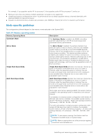
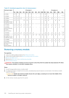
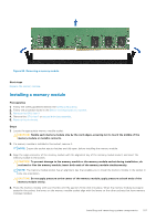
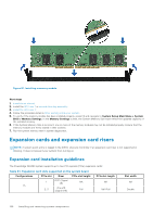
Figure 81. Installing a memory module Next steps 1. Install the air shroud. 2. Install the GPU riser 1 or second drive bay assembly. 3. Install the GPU riser 2. 4. Follow the procedure listed in After working inside your system. 5. To verify if the memory module has been installed properly, press F2 and navigate to System Setup Main Menu > System BIOS > Memory Settings. In the Memory Settings screen, the System Memory Size must reflect the updated capacity of the installed memory. 6. If the System Memory Size is incorrect, one or more of the memory modules may not be installed properly. Ensure that the memory modules are firmly seated in their sockets. 7. Run the system memory test in system diagnostics. Expansion cards and expansion card risers NOTE: A system event entry is logged in the iDRAC Lifecycle Controller if an expansion card riser is not supported or missing. It does not prevent your system from turning on. Expansion card installation guidelines The PowerEdge XE2420 system supports up to two PCI express (PCIe) expansion cards: Table 44. Expansion card slots supported on the system board Configurations 1A PCIe slot 1 2, 3 Riser OCP (Signal x8) One x16 (Signal x16) PCIe slot height NA Full PCIe slot length NA Half/Full Slot width NA Double 108 Installing and removing system components
-
 1
1 -
2
-
3
-
4
-
5
-
6
-
7
-
8
-
9
-
10
-
11
-
12
-
13
-
14
-
15
-
16
-
17
-
18
-
19
-
20
-
21
-
22
-
23
-
24
-
25
-
26
-
27
-
28
-
29
-
30
-
31
-
32
-
33
-
34
-
35
-
36
-
37
-
38
-
39
-
40
-
41
-
42
-
43
-
44
-
45
-
46
-
47
-
48
-
49
-
50
-
51
-
52
-
53
-
54
-
55
-
56
-
57
-
58
-
59
-
60
-
61
-
62
-
63
-
64
-
65
-
66
-
67
-
68
-
69
-
70
-
71
-
72
-
73
-
74
-
75
-
76
-
77
-
78
-
79
-
80
-
81
-
82
-
83
-
84
-
85
-
86
-
87
-
88
-
89
-
90
-
91
-
92
-
93
-
94
-
95
-
96
-
97
-
98
-
99
-
100
-
101
-
102
-
 103
103 -
 104
104 -
 105
105 -
 106
106 -
 107
107 -
 108
108 -
 109
109 -
 110
110 -
 111
111 -
 112
112 -
 113
113 -
114
-
115
-
116
-
117
-
118
-
119
-
120
-
121
-
122
-
123
-
124
-
125
-
126
-
127
-
128
-
129
-
130
-
131
-
132
-
133
-
134
-
135
-
136
-
137
-
138
-
139
-
140
-
141
-
142
-
143
-
144
-
145
-
146
-
147
-
148
-
149
-
150
-
151
-
152
-
153
-
154
-
155
-
156
-
157
-
158
-
159
-
160
-
161
-
162
-
163
-
164
-
165
-
166
-
167
-
168
-
169
-
170
-
171
-
172
-
173
-
174
-
175
-
176
-
177
 |
 |
