Dell PowerEdge XE2420 EMC Installation and Service Manual - Page 146
Take care not to damage the system identification button while removing the system board
 |
View all Dell PowerEdge XE2420 manuals
Add to My Manuals
Save this manual to your list of manuals |
Page 146 highlights
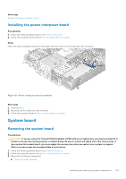
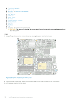
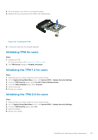
b. Control panel assembly c. GPU riser 2 d. GPU riser 1 or Second drive bay assembly e. Interposer f. LOM riser card g. NVME riser h. IDSDM module i. Air shroud j. Internal USB key (if installed) k. Memory modules l. Heat sink m. Processor n. TPM o. Disconnect all cables from the system board. CAUTION: Take care not to damage the system identification button while removing the system board from the system. Steps 1. Using a Phillips #2 screwdriver, remove the screws securing the system board to the chassis. Figure 122. System board diagram with screws 2. Using the system board holder, slightly lift the system board, and then slide it toward the rear of the chassis. 3. Lift the system board out of the chassis. 146 Installing and removing system components
-
 1
1 -
2
-
3
-
4
-
5
-
6
-
7
-
8
-
9
-
10
-
11
-
12
-
13
-
14
-
15
-
16
-
17
-
18
-
19
-
20
-
21
-
22
-
23
-
24
-
25
-
26
-
27
-
28
-
29
-
30
-
31
-
32
-
33
-
34
-
35
-
36
-
37
-
38
-
39
-
40
-
41
-
42
-
43
-
44
-
45
-
46
-
47
-
48
-
49
-
50
-
51
-
52
-
53
-
54
-
55
-
56
-
57
-
58
-
59
-
60
-
61
-
62
-
63
-
64
-
65
-
66
-
67
-
68
-
69
-
70
-
71
-
72
-
73
-
74
-
75
-
76
-
77
-
78
-
79
-
80
-
81
-
82
-
83
-
84
-
85
-
86
-
87
-
88
-
89
-
90
-
91
-
92
-
93
-
94
-
95
-
96
-
97
-
98
-
99
-
100
-
101
-
102
-
103
-
104
-
105
-
106
-
107
-
108
-
109
-
110
-
111
-
112
-
113
-
114
-
115
-
116
-
117
-
118
-
119
-
120
-
121
-
122
-
123
-
124
-
125
-
126
-
127
-
128
-
129
-
130
-
131
-
132
-
133
-
134
-
135
-
136
-
137
-
138
-
139
-
140
-
 141
141 -
 142
142 -
 143
143 -
 144
144 -
 145
145 -
 146
146 -
 147
147 -
 148
148 -
 149
149 -
 150
150 -
 151
151 -
152
-
153
-
154
-
155
-
156
-
157
-
158
-
159
-
160
-
161
-
162
-
163
-
164
-
165
-
166
-
167
-
168
-
169
-
170
-
171
-
172
-
173
-
174
-
175
-
176
-
177
 |
 |
