Dell PowerEdge XE2420 EMC Installation and Service Manual - Page 104
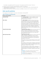
Optimizer Mode, Memory Operating Mode, Description, Dell Fault Resilient Mode, Processor
 |
View all Dell PowerEdge XE2420 manuals
Add to My Manuals
Save this manual to your list of manuals |
Page 104 highlights
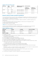
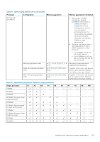
Table 40. Memory operating modes (continued) Memory Operating Mode Dell Fault Resilient Mode Description The Dell Fault Resilient Mode if enabled, the BIOS creates an area of memory that is fault resilient. This mode can be used by an OS that supports the feature to load critical applications or enables the OS kernel to maximize system availability. NOTE: This feature is only supported in Gold and Platinum Intel processors. NOTE: Memory configuration has to be of same size DIMM, speed, and rank. Optimizer Mode This mode supports Single Device Data Correction (SDDC) only for memory modules that use x4 device width. It does not impose any specific slot population requirements. ● Dual processor: Populate the slots in round robin sequence starting with processor 1. NOTE: Processor 1 and processor 2 population should match. Table 41. Memory population rules Processor Configuration Single processor Optimizer (Independent channel) population order Mirror population order Single rank sparing population order Multi rank sparing population order Dual processor Optimized (Independent (Populate round robin channel) population order Memory population 1, 2, 3, 4, 5, 6, 7, 8, 9, 10 {1, 2, 3, 4, 5, 6} 1, 2, 3, 4, 5, 6, 7, 8, 9, 10 1, 2, 3, 4, 5, 6, 7, 8, 9, 10 A{1}, B{1}, A{2}, B{2}, A{3}, B{3}... Memory population information ● Populate in this order, odd amount allowed. ● Odd number of DIMM population is allowed. NOTE: Odd number of DIMMs will result in unbalanced memory configurations, which in turn will result in performance loss. It is recommended to populate all memory channels identically with identical DIMMs for best performance. ● Optimizer population order is not traditional for 4 and 8 DIMM installations of single processor. ○ For 4 DIMMs: A1, A2, A4, A5 ○ For 8 DIMMs: A1, A2, A4, A5, A7, A8, A9, A10 Mirroring is supported with 6 DIMM slots per processor. Populate in this order, odd amount allowed. Requires two ranks or more per channel. Populate in this order, odd amount allowed. Requires three ranks or more per channel. ● Odd amount of DIMM slots per processor allowed. 104 Installing and removing system components
-
 1
1 -
2
-
3
-
4
-
5
-
6
-
7
-
8
-
9
-
10
-
11
-
12
-
13
-
14
-
15
-
16
-
17
-
18
-
19
-
20
-
21
-
22
-
23
-
24
-
25
-
26
-
27
-
28
-
29
-
30
-
31
-
32
-
33
-
34
-
35
-
36
-
37
-
38
-
39
-
40
-
41
-
42
-
43
-
44
-
45
-
46
-
47
-
48
-
49
-
50
-
51
-
52
-
53
-
54
-
55
-
56
-
57
-
58
-
59
-
60
-
61
-
62
-
63
-
64
-
65
-
66
-
67
-
68
-
69
-
70
-
71
-
72
-
73
-
74
-
75
-
76
-
77
-
78
-
79
-
80
-
81
-
82
-
83
-
84
-
85
-
86
-
87
-
88
-
89
-
90
-
91
-
92
-
93
-
94
-
95
-
96
-
97
-
98
-
 99
99 -
 100
100 -
 101
101 -
 102
102 -
 103
103 -
 104
104 -
 105
105 -
 106
106 -
 107
107 -
 108
108 -
 109
109 -
110
-
111
-
112
-
113
-
114
-
115
-
116
-
117
-
118
-
119
-
120
-
121
-
122
-
123
-
124
-
125
-
126
-
127
-
128
-
129
-
130
-
131
-
132
-
133
-
134
-
135
-
136
-
137
-
138
-
139
-
140
-
141
-
142
-
143
-
144
-
145
-
146
-
147
-
148
-
149
-
150
-
151
-
152
-
153
-
154
-
155
-
156
-
157
-
158
-
159
-
160
-
161
-
162
-
163
-
164
-
165
-
166
-
167
-
168
-
169
-
170
-
171
-
172
-
173
-
174
-
175
-
176
-
177
 |
 |
