Dell PowerEdge XE2420 EMC Installation and Service Manual - Page 107
Installing a memory module, Removing a memory module
 |
View all Dell PowerEdge XE2420 manuals
Add to My Manuals
Save this manual to your list of manuals |
Page 107 highlights
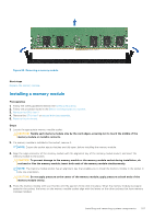
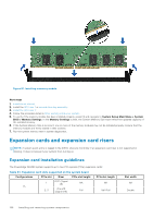
Figure 80. Removing a memory module Next steps Replace the memory module. Installing a memory module Prerequisites 1. Follow the safety guidelines listed in the Safety instructions. 2. Follow the procedure listed in the Before working inside your system. 3. Remove the GPU riser 2. 4. Remove the GPU riser 1 or second drive bay assembly. 5. Remove the air shroud. Steps 1. Locate the appropriate memory module socket. CAUTION: Handle each memory module only by the card edges, ensuring not to touch the middle of the memory module or metallic contacts. 2. If a memory module is installed in the socket, remove it. NOTE: Ensure the socket ejector latches are fully open, before installing the memory module. 3. Align the edge connector of the memory module with the alignment key of the memory module socket, and insert the memory module in the socket. CAUTION: To prevent damage to the memory module or the memory module socket during installation, do not bend or flex the memory module; insert both ends of the memory module simultaneously. NOTE: The memory module socket has an alignment key that enables you to install the memory module in the socket in only one orientation. CAUTION: Do not apply pressure at the center of the memory module; apply pressure at both ends of the memory module evenly. 4. Press the memory module with your thumbs until the ejectors firmly click into place. When the memory module is properly seated in the socket, the levers on the memory module socket align with the levers on the other sockets that have memory modules installed. Installing and removing system components 107
-
 1
1 -
2
-
3
-
4
-
5
-
6
-
7
-
8
-
9
-
10
-
11
-
12
-
13
-
14
-
15
-
16
-
17
-
18
-
19
-
20
-
21
-
22
-
23
-
24
-
25
-
26
-
27
-
28
-
29
-
30
-
31
-
32
-
33
-
34
-
35
-
36
-
37
-
38
-
39
-
40
-
41
-
42
-
43
-
44
-
45
-
46
-
47
-
48
-
49
-
50
-
51
-
52
-
53
-
54
-
55
-
56
-
57
-
58
-
59
-
60
-
61
-
62
-
63
-
64
-
65
-
66
-
67
-
68
-
69
-
70
-
71
-
72
-
73
-
74
-
75
-
76
-
77
-
78
-
79
-
80
-
81
-
82
-
83
-
84
-
85
-
86
-
87
-
88
-
89
-
90
-
91
-
92
-
93
-
94
-
95
-
96
-
97
-
98
-
99
-
100
-
101
-
 102
102 -
 103
103 -
 104
104 -
 105
105 -
 106
106 -
 107
107 -
 108
108 -
 109
109 -
 110
110 -
 111
111 -
 112
112 -
113
-
114
-
115
-
116
-
117
-
118
-
119
-
120
-
121
-
122
-
123
-
124
-
125
-
126
-
127
-
128
-
129
-
130
-
131
-
132
-
133
-
134
-
135
-
136
-
137
-
138
-
139
-
140
-
141
-
142
-
143
-
144
-
145
-
146
-
147
-
148
-
149
-
150
-
151
-
152
-
153
-
154
-
155
-
156
-
157
-
158
-
159
-
160
-
161
-
162
-
163
-
164
-
165
-
166
-
167
-
168
-
169
-
170
-
171
-
172
-
173
-
174
-
175
-
176
-
177
 |
 |
