Dell PowerEdge XE2420 EMC Installation and Service Manual - Page 143
Optional internal USB memory key, Power interposer board
 |
View all Dell PowerEdge XE2420 manuals
Add to My Manuals
Save this manual to your list of manuals |
Page 143 highlights
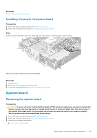
Next steps 1. If applicable, connect the cables to the expansion card on the interposer. 2. Install the interposer 3. Install the GPU riser 2 4. If applicable, connect the cables to the GPU. 5. Follow the procedure listed in the After working inside your system. 6. Confirm that the battery is operating properly, by performing the following steps: a. Enter the System Setup, while booting, by pressing F2. b. Enter the correct time and date in the System Setup Time and Date fields. c. Exit the System Setup. d. To test the newly installed battery, remove the system from the enclosure for at least an hour. e. Reinstall the system into the enclosure after an hour. f. Enter the System Setup and if the time and date are still incorrect, see Getting help section. Optional internal USB memory key NOTE: To locate the internal USB port on the system board, see the System board jumpers and connectors section. Replacing optional internal USB memory key Prerequisites CAUTION: To avoid interference with other components in the server, the maximum permissible dimensions of the USB memory key are 15.9 mm wide x 57.15 mm long x 7.9 mm high. 1. Follow the safety guidelines listed in the Safety instructions. 2. Follow the procedure listed in the Before working inside your system. 3. Remove the interposer. Steps 1. Locate the USB port or USB memory key on the system board. To locate the internal USB port on the system board, see the System board jumpers and connectors section. 2. If installed, remove the USB memory key from the USB port. 3. Insert the replacement USB memory key into the USB port. Next steps 1. Install the interposer. 2. Follow the procedure listed in After working inside your system. 3. While booting, press F2 to enter System Setup and verify that the system detects the USB memory key. Power interposer board Power interposer board The power interposer board (PIB) is a board that connects the hot swappable power supply units (PSUs) to the system board. The PIB is only supported in systems with redundant PSUs. Installing and removing system components 143
-
 1
1 -
2
-
3
-
4
-
5
-
6
-
7
-
8
-
9
-
10
-
11
-
12
-
13
-
14
-
15
-
16
-
17
-
18
-
19
-
20
-
21
-
22
-
23
-
24
-
25
-
26
-
27
-
28
-
29
-
30
-
31
-
32
-
33
-
34
-
35
-
36
-
37
-
38
-
39
-
40
-
41
-
42
-
43
-
44
-
45
-
46
-
47
-
48
-
49
-
50
-
51
-
52
-
53
-
54
-
55
-
56
-
57
-
58
-
59
-
60
-
61
-
62
-
63
-
64
-
65
-
66
-
67
-
68
-
69
-
70
-
71
-
72
-
73
-
74
-
75
-
76
-
77
-
78
-
79
-
80
-
81
-
82
-
83
-
84
-
85
-
86
-
87
-
88
-
89
-
90
-
91
-
92
-
93
-
94
-
95
-
96
-
97
-
98
-
99
-
100
-
101
-
102
-
103
-
104
-
105
-
106
-
107
-
108
-
109
-
110
-
111
-
112
-
113
-
114
-
115
-
116
-
117
-
118
-
119
-
120
-
121
-
122
-
123
-
124
-
125
-
126
-
127
-
128
-
129
-
130
-
131
-
132
-
133
-
134
-
135
-
136
-
137
-
 138
138 -
 139
139 -
 140
140 -
 141
141 -
 142
142 -
 143
143 -
 144
144 -
 145
145 -
 146
146 -
 147
147 -
 148
148 -
149
-
150
-
151
-
152
-
153
-
154
-
155
-
156
-
157
-
158
-
159
-
160
-
161
-
162
-
163
-
164
-
165
-
166
-
167
-
168
-
169
-
170
-
171
-
172
-
173
-
174
-
175
-
176
-
177
 |
 |
