Dell PowerEdge XE2420 EMC Installation and Service Manual - Page 94
Cable routing
 |
View all Dell PowerEdge XE2420 manuals
Add to My Manuals
Save this manual to your list of manuals |
Page 94 highlights
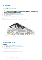
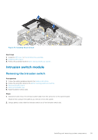
Next steps 1. Reconnect the control panel cable to the control panel connector. 2. Replace the primary drive backplane assembly. 3. Follow the procedure listed in the After working inside your system. Cable routing Figure 70. Cable routing - 2 x 2.5-inch drive backplane Figure 71. Cable routing - 4 x 2.5-inch drive backplane 94 Installing and removing system components
-
 1
1 -
2
-
3
-
4
-
5
-
6
-
7
-
8
-
9
-
10
-
11
-
12
-
13
-
14
-
15
-
16
-
17
-
18
-
19
-
20
-
21
-
22
-
23
-
24
-
25
-
26
-
27
-
28
-
29
-
30
-
31
-
32
-
33
-
34
-
35
-
36
-
37
-
38
-
39
-
40
-
41
-
42
-
43
-
44
-
45
-
46
-
47
-
48
-
49
-
50
-
51
-
52
-
53
-
54
-
55
-
56
-
57
-
58
-
59
-
60
-
61
-
62
-
63
-
64
-
65
-
66
-
67
-
68
-
69
-
70
-
71
-
72
-
73
-
74
-
75
-
76
-
77
-
78
-
79
-
80
-
81
-
82
-
83
-
84
-
85
-
86
-
87
-
88
-
 89
89 -
 90
90 -
 91
91 -
 92
92 -
 93
93 -
 94
94 -
 95
95 -
 96
96 -
 97
97 -
 98
98 -
 99
99 -
100
-
101
-
102
-
103
-
104
-
105
-
106
-
107
-
108
-
109
-
110
-
111
-
112
-
113
-
114
-
115
-
116
-
117
-
118
-
119
-
120
-
121
-
122
-
123
-
124
-
125
-
126
-
127
-
128
-
129
-
130
-
131
-
132
-
133
-
134
-
135
-
136
-
137
-
138
-
139
-
140
-
141
-
142
-
143
-
144
-
145
-
146
-
147
-
148
-
149
-
150
-
151
-
152
-
153
-
154
-
155
-
156
-
157
-
158
-
159
-
160
-
161
-
162
-
163
-
164
-
165
-
166
-
167
-
168
-
169
-
170
-
171
-
172
-
173
-
174
-
175
-
176
-
177
 |
 |

Next steps
1.
Reconnect the control panel cable to the control panel connector.
2.
Replace the primary drive backplane assembly
.
3.
Follow the procedure listed in the
After working inside your system
.
Cable routing
Figure 70. Cable routing - 2 x 2.5-inch drive backplane
Figure 71. Cable routing - 4 x 2.5-inch drive backplane
94
Installing and removing system components