Dell PowerEdge XE2420 EMC Installation and Service Manual - Page 141
Installing the network daughter card, Prerequisites, Steps, Next steps
 |
View all Dell PowerEdge XE2420 manuals
Add to My Manuals
Save this manual to your list of manuals |
Page 141 highlights
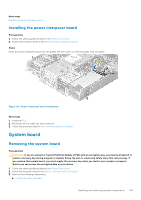
Installing the network daughter card Prerequisites 1. Follow the safety guidelines listed in the Safety instructions. 2. Follow the procedure listed in the Before working inside your system. 3. If applicable, disconnect the cables connected to the GPU risers. 4. Remove the GPU riser 2. 5. Remove the interposer. Steps 1. Remove the LOM filler bracket. a. Using the Phillips #2 screwdriver, remove the screw that secures the bracket to the system. b. Slide the bracket out of the slot on the system. 2. Install the LOM bracket. a. Insert and slide the LOM bracket into the slot on the system. b. Using the Phillips #2 screwdriver, secure the bracket to the system with a screw 3. Orient the network daughter card to fit the Ethernet connectors or the SFP+ through the slot of the bracket. NOTE: NIC port 1 in network daughter card is Gb3, and NIC port 2 is Gb4. 4. Press the network daughter card until the card is firmly seated on the system board connector and the two blue plastic clips to secure the card in place. 5. Using a Phillips #2 screwdriver, secure the network daughter card to the system board with screws. Figure 116. Installing the network daughter card Next steps 1. Install the interposer. 2. Install the GPU riser 2. 3. If applicable, connect the cables connected to the GPU risers. 4. Follow the procedure listed in After working inside your system. NOTE: While replacing faulty storage controller/FC/NIC card with the same type of card, after you power on the system; the new card automatically updates to the same firmware and configuration of the faulty one. For more information about the Part replacement configuration, see the Lifecycle Controller User's Guide at www.dell.com/idracmanuals Installing and removing system components 141
-
 1
1 -
2
-
3
-
4
-
5
-
6
-
7
-
8
-
9
-
10
-
11
-
12
-
13
-
14
-
15
-
16
-
17
-
18
-
19
-
20
-
21
-
22
-
23
-
24
-
25
-
26
-
27
-
28
-
29
-
30
-
31
-
32
-
33
-
34
-
35
-
36
-
37
-
38
-
39
-
40
-
41
-
42
-
43
-
44
-
45
-
46
-
47
-
48
-
49
-
50
-
51
-
52
-
53
-
54
-
55
-
56
-
57
-
58
-
59
-
60
-
61
-
62
-
63
-
64
-
65
-
66
-
67
-
68
-
69
-
70
-
71
-
72
-
73
-
74
-
75
-
76
-
77
-
78
-
79
-
80
-
81
-
82
-
83
-
84
-
85
-
86
-
87
-
88
-
89
-
90
-
91
-
92
-
93
-
94
-
95
-
96
-
97
-
98
-
99
-
100
-
101
-
102
-
103
-
104
-
105
-
106
-
107
-
108
-
109
-
110
-
111
-
112
-
113
-
114
-
115
-
116
-
117
-
118
-
119
-
120
-
121
-
122
-
123
-
124
-
125
-
126
-
127
-
128
-
129
-
130
-
131
-
132
-
133
-
134
-
135
-
 136
136 -
 137
137 -
 138
138 -
 139
139 -
 140
140 -
 141
141 -
 142
142 -
 143
143 -
 144
144 -
 145
145 -
 146
146 -
147
-
148
-
149
-
150
-
151
-
152
-
153
-
154
-
155
-
156
-
157
-
158
-
159
-
160
-
161
-
162
-
163
-
164
-
165
-
166
-
167
-
168
-
169
-
170
-
171
-
172
-
173
-
174
-
175
-
176
-
177
 |
 |
