Dell PowerEdge XE2420 EMC Installation and Service Manual - Page 11
Table 1. Front view of 2 x 2.5-inch drive system continued, Table 2. Front view of 4 x 2.5-inch
 |
View all Dell PowerEdge XE2420 manuals
Add to My Manuals
Save this manual to your list of manuals |
Page 11 highlights
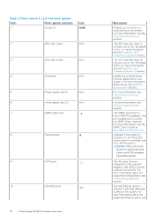
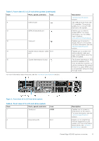
Table 1. Front view of 2 x 2.5-inch drive system (continued) Item Ports, panels, and slots Icon 11 USB 3.0 port 12 iDRAC9 dedicated port 13 VGA port 14 System status indicator cable N/A port 15 System identification button For more information about the ports, see the Technical Specifications section. Description Technical specifications section. The USB ports are 9-pin and 3.0-compliant. These ports enable you to connect USB devices to the system. Enables you to remotely access iDRAC. For more information, see the iDRAC User's Guide at www.dell.com/idracmanuals Enables you to connect a display device to the system. For more information, see the Technical specifications section. Enables you to connect the status indicator cable and view system status when the CMA is installed. The System Identification (ID) button is available on the front to identify a system in a rack by turning on the system ID button to reset iDRAC and to access BIOS using the step through mode. Figure 2. Front view of 4 x 2.5-inch drive system Table 2. Front view of 4 x 2.5-inch drive system Item Ports, panels, and slots 1 Serial port Icon IOIOI 2 Drive slots (2,3) N/A Description Enables you to connect a serial device to the system. For more information, see the Technical specifications section. Enable you to install drives that are supported on your system. For more information about drives, see Technical specifications section. PowerEdge XE2420 system overview 11
-
 1
1 -
2
-
3
-
4
-
5
-
 6
6 -
 7
7 -
 8
8 -
 9
9 -
 10
10 -
 11
11 -
 12
12 -
 13
13 -
 14
14 -
 15
15 -
 16
16 -
17
-
18
-
19
-
20
-
21
-
22
-
23
-
24
-
25
-
26
-
27
-
28
-
29
-
30
-
31
-
32
-
33
-
34
-
35
-
36
-
37
-
38
-
39
-
40
-
41
-
42
-
43
-
44
-
45
-
46
-
47
-
48
-
49
-
50
-
51
-
52
-
53
-
54
-
55
-
56
-
57
-
58
-
59
-
60
-
61
-
62
-
63
-
64
-
65
-
66
-
67
-
68
-
69
-
70
-
71
-
72
-
73
-
74
-
75
-
76
-
77
-
78
-
79
-
80
-
81
-
82
-
83
-
84
-
85
-
86
-
87
-
88
-
89
-
90
-
91
-
92
-
93
-
94
-
95
-
96
-
97
-
98
-
99
-
100
-
101
-
102
-
103
-
104
-
105
-
106
-
107
-
108
-
109
-
110
-
111
-
112
-
113
-
114
-
115
-
116
-
117
-
118
-
119
-
120
-
121
-
122
-
123
-
124
-
125
-
126
-
127
-
128
-
129
-
130
-
131
-
132
-
133
-
134
-
135
-
136
-
137
-
138
-
139
-
140
-
141
-
142
-
143
-
144
-
145
-
146
-
147
-
148
-
149
-
150
-
151
-
152
-
153
-
154
-
155
-
156
-
157
-
158
-
159
-
160
-
161
-
162
-
163
-
164
-
165
-
166
-
167
-
168
-
169
-
170
-
171
-
172
-
173
-
174
-
175
-
176
-
177
 |
 |
