Dell PowerEdge XE2420 EMC Installation and Service Manual - Page 106
Removing a memory module, Table 43. Optimized population rules for dual processor
 |
View all Dell PowerEdge XE2420 manuals
Add to My Manuals
Save this manual to your list of manuals |
Page 106 highlights
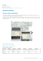
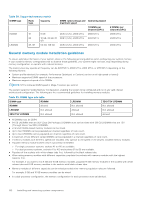
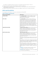
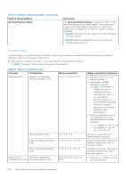
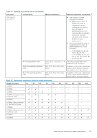
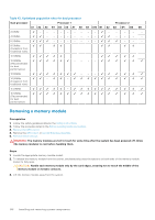
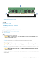
Table 43. Optimized population rules for dual processor Dual processor Processor 1 Processor 2 A1 A2 A3 A4 A5 A6 A7 A8 A9 A10 B1 B2 B3 B4 B5 B6 2 DIMM - - - - 4 DIMMs - - - - 6 DIMMs - - - 8 DIMMs - ✔ ✔ - (Exception from traditional rules) 10 DIMMs ✔ ✔ - 12 DIMMs ✔ ✔ ✔ (Recommended for best performance) 13 DIMMs ✔ ✔ ✔ 14 DIMMs ✔ ✔ ✔ (Exception from traditional rules) 15 DIMMs ✔ ✔ ✔ 16 DIMMs ✔ ✔ ✔ (Recommended for best performance) Removing a memory module Prerequisites 1. Follow the safety guidelines listed in the Safety instructions. 2. Follow the procedure listed in the Before working inside your system. 3. Remove the GPU riser 2. 4. Remove the GPU riser 1 or second drive bay assembly. 5. Remove the air shroud. WARNING: The memory modules are hot to touch for some time after the system has been powered off. Allow the memory modules to cool before handling them. Steps 1. Locate the appropriate memory module socket. 2. To release the memory module from the socket, simultaneously press the ejectors on both ends of the memory module socket to fully open. CAUTION: Handle each memory module only by the card edges, ensuring not to touch the middle of the memory module or metallic contacts. 3. Lift the memory module away from the system. 106 Installing and removing system components
-
 1
1 -
2
-
3
-
4
-
5
-
6
-
7
-
8
-
9
-
10
-
11
-
12
-
13
-
14
-
15
-
16
-
17
-
18
-
19
-
20
-
21
-
22
-
23
-
24
-
25
-
26
-
27
-
28
-
29
-
30
-
31
-
32
-
33
-
34
-
35
-
36
-
37
-
38
-
39
-
40
-
41
-
42
-
43
-
44
-
45
-
46
-
47
-
48
-
49
-
50
-
51
-
52
-
53
-
54
-
55
-
56
-
57
-
58
-
59
-
60
-
61
-
62
-
63
-
64
-
65
-
66
-
67
-
68
-
69
-
70
-
71
-
72
-
73
-
74
-
75
-
76
-
77
-
78
-
79
-
80
-
81
-
82
-
83
-
84
-
85
-
86
-
87
-
88
-
89
-
90
-
91
-
92
-
93
-
94
-
95
-
96
-
97
-
98
-
99
-
100
-
 101
101 -
 102
102 -
 103
103 -
 104
104 -
 105
105 -
 106
106 -
 107
107 -
 108
108 -
 109
109 -
 110
110 -
 111
111 -
112
-
113
-
114
-
115
-
116
-
117
-
118
-
119
-
120
-
121
-
122
-
123
-
124
-
125
-
126
-
127
-
128
-
129
-
130
-
131
-
132
-
133
-
134
-
135
-
136
-
137
-
138
-
139
-
140
-
141
-
142
-
143
-
144
-
145
-
146
-
147
-
148
-
149
-
150
-
151
-
152
-
153
-
154
-
155
-
156
-
157
-
158
-
159
-
160
-
161
-
162
-
163
-
164
-
165
-
166
-
167
-
168
-
169
-
170
-
171
-
172
-
173
-
174
-
175
-
176
-
177
 |
 |
