Dell PowerEdge XE2420 EMC Installation and Service Manual - Page 44
Serial Communication, Table 23. Integrated Devices details continued
 |
View all Dell PowerEdge XE2420 manuals
Add to My Manuals
Save this manual to your list of manuals |
Page 44 highlights
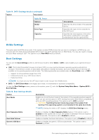
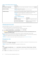
Table 23. Integrated Devices details (continued) Option Description Memory Mapped I/O above 4 GB Enables or disables the support for the PCIe devices that need large amounts of memory. Enable this option only for 64-bit operating systems. This option is set to Enabled by default. Memory Mapped I/O Base When set to 12 TB, the system maps the MMIO base to 12 TB. Enable this option for an OS that requires 44 bit PCIe addressing. When set to 512 GB, the system maps the MMIO base to 512 GB, and reduces the maximum support for memory to less than 512 GB. Enable this option only for the 4 GPU DGMA issue. This option is set to 56 TB by default. Slot Disablement Enables or disables the available PCIe slots on your system. The slot disablement feature controls the configuration of the PCIe cards installed in the specified slot. Slots must be disabled only when the installed peripheral card prevents booting into the operating system or causes delays in system startup. If the slot is disabled, both the Option ROM and UEFI drivers are disabled. Only slots that are present on the system will be available for control. Slot n: Enables or disables or only the boot driver is disabled for the PCIe slot n. This option is set to Enabled by default. Slot Bifurcation Slot Discovery Bifurcation Settings allows Platform Default Bifurcation and Manual bifurcation Control. The default is set to Platform Default Bifurcation. The slot bifurcation field is accessible when set to Manual bifurcation Control and is grayed out when set to Platform Default Bifurcation. Serial Communication To view the Serial Communication screen, power on the system, press F2, and click System Setup Main Menu > System BIOS > Serial Communication. Table 24. Serial Communication details Option Description Serial Communication Selects serial communication devices (Serial Device 1 and Serial Device 2) in BIOS. BIOS console redirection can also be enabled, and the port address can be specified. This option is set to Auto by default. Serial Port Address Enables you to set the port address for serial devices. . This field sets the serial port address to either COM1 or COM2 (COM1=0x3F8, COM2=0x2F8). NOTE: You can use only Serial Device 2 for the Serial Over LAN (SOL) feature. To use console redirection by SOL, configure the same port address for console redirection and the serial device. NOTE: Every time the system boots, the BIOS syncs the serial MUX setting that is saved in iDRAC. The serial MUX setting can independently be changed in iDRAC. Loading the BIOS default settings from within the BIOS setup utility may not always revert the serial MUX setting to the default setting of Serial Device 1. External Serial Connector Enables you to associate the External Serial Connector to Serial Device 1, Serial Device 2, or the Remote Access Device by using this option. This option is set to Serial Device 1 by default. NOTE: Only Serial Device 2 can be used for Serial Over LAN (SOL). To use console redirection by SOL, configure the same port address for console redirection and the serial device. NOTE: Every time the system boots, the BIOS syncs the serial MUX setting saved in iDRAC. The serial MUX setting can independently be changed in iDRAC. Loading the BIOS default settings from within the BIOS 44 Pre-operating system management applications
-
 1
1 -
2
-
3
-
4
-
5
-
6
-
7
-
8
-
9
-
10
-
11
-
12
-
13
-
14
-
15
-
16
-
17
-
18
-
19
-
20
-
21
-
22
-
23
-
24
-
25
-
26
-
27
-
28
-
29
-
30
-
31
-
32
-
33
-
34
-
35
-
36
-
37
-
38
-
 39
39 -
 40
40 -
 41
41 -
 42
42 -
 43
43 -
 44
44 -
 45
45 -
 46
46 -
 47
47 -
 48
48 -
 49
49 -
50
-
51
-
52
-
53
-
54
-
55
-
56
-
57
-
58
-
59
-
60
-
61
-
62
-
63
-
64
-
65
-
66
-
67
-
68
-
69
-
70
-
71
-
72
-
73
-
74
-
75
-
76
-
77
-
78
-
79
-
80
-
81
-
82
-
83
-
84
-
85
-
86
-
87
-
88
-
89
-
90
-
91
-
92
-
93
-
94
-
95
-
96
-
97
-
98
-
99
-
100
-
101
-
102
-
103
-
104
-
105
-
106
-
107
-
108
-
109
-
110
-
111
-
112
-
113
-
114
-
115
-
116
-
117
-
118
-
119
-
120
-
121
-
122
-
123
-
124
-
125
-
126
-
127
-
128
-
129
-
130
-
131
-
132
-
133
-
134
-
135
-
136
-
137
-
138
-
139
-
140
-
141
-
142
-
143
-
144
-
145
-
146
-
147
-
148
-
149
-
150
-
151
-
152
-
153
-
154
-
155
-
156
-
157
-
158
-
159
-
160
-
161
-
162
-
163
-
164
-
165
-
166
-
167
-
168
-
169
-
170
-
171
-
172
-
173
-
174
-
175
-
176
-
177
 |
 |
