Dell PowerEdge XE2420 EMC Installation and Service Manual - Page 144
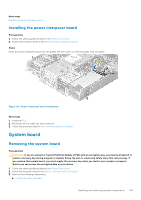
Removing the power interposer board
 |
View all Dell PowerEdge XE2420 manuals
Add to My Manuals
Save this manual to your list of manuals |
Page 144 highlights
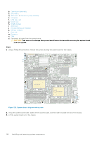
Figure 119. Power interposer board 1. FAN_SIG (PIB to cooling fans board) 3. BP1_PWR (PIB to primary backplane) 5. FAN_PWR (PIB to cooling fan board) 7. GPU2_PWR (PIB to GPU 2) 2. SLOT4_PWR (PIB to system board) 4. BP2_PWR (PIB to Second backplane) 6. GPU1_PWR (PIB to GPU 1) 8. SLOT1_PWR (PIB to system board) Removing the power interposer board Prerequisites 1. Follow the safety guidelines listed in the Safety instructions. 2. Follow the procedure listed in the Before working inside your system. 3. Remove the power supply units. 4. Remove all the cables connected to the power interposer board. NOTE: Observe the routing of the cable as you remove it from the power interposer board. Steps 1. Pull the plunger to disengage the power interposer board from the lock hole on the PSU cage. 2. Lift the power interposer board out of the chassis. Figure 120. Power interposer removal 144 Installing and removing system components
-
 1
1 -
2
-
3
-
4
-
5
-
6
-
7
-
8
-
9
-
10
-
11
-
12
-
13
-
14
-
15
-
16
-
17
-
18
-
19
-
20
-
21
-
22
-
23
-
24
-
25
-
26
-
27
-
28
-
29
-
30
-
31
-
32
-
33
-
34
-
35
-
36
-
37
-
38
-
39
-
40
-
41
-
42
-
43
-
44
-
45
-
46
-
47
-
48
-
49
-
50
-
51
-
52
-
53
-
54
-
55
-
56
-
57
-
58
-
59
-
60
-
61
-
62
-
63
-
64
-
65
-
66
-
67
-
68
-
69
-
70
-
71
-
72
-
73
-
74
-
75
-
76
-
77
-
78
-
79
-
80
-
81
-
82
-
83
-
84
-
85
-
86
-
87
-
88
-
89
-
90
-
91
-
92
-
93
-
94
-
95
-
96
-
97
-
98
-
99
-
100
-
101
-
102
-
103
-
104
-
105
-
106
-
107
-
108
-
109
-
110
-
111
-
112
-
113
-
114
-
115
-
116
-
117
-
118
-
119
-
120
-
121
-
122
-
123
-
124
-
125
-
126
-
127
-
128
-
129
-
130
-
131
-
132
-
133
-
134
-
135
-
136
-
137
-
138
-
 139
139 -
 140
140 -
 141
141 -
 142
142 -
 143
143 -
 144
144 -
 145
145 -
 146
146 -
 147
147 -
 148
148 -
 149
149 -
150
-
151
-
152
-
153
-
154
-
155
-
156
-
157
-
158
-
159
-
160
-
161
-
162
-
163
-
164
-
165
-
166
-
167
-
168
-
169
-
170
-
171
-
172
-
173
-
174
-
175
-
176
-
177
 |
 |
