HP Z200 HP Z200 SFF Workstation Maintenance and Service Guide
HP Z200 - Small Form Factor Workstation Manual
 |
View all HP Z200 manuals
Add to My Manuals
Save this manual to your list of manuals |
HP Z200 manual content summary:
- HP Z200 | HP Z200 SFF Workstation Maintenance and Service Guide - Page 1
HP Z200 Small Form Factor Workstation Maintenance and Service Guide - HP Z200 | HP Z200 SFF Workstation Maintenance and Service Guide - Page 2
liable for technical or editorial errors or omissions contained herein or change without notice. The warranties for HP products are set forth in the is protected by copyright. No part of this document may be Packard Company. Trademark Credits Microsoft, Windows, and XP are U.S. registered trademarks - HP Z200 | HP Z200 SFF Workstation Maintenance and Service Guide - Page 3
for the HP Z200 Small Form Factor (SFF) Workstation. It includes these topics: Guide topics Product overview on page 1 Setting up the operating system on page 16 Restoring the operating system on page 22 System management on page 28 Replacing components on page 59 Diagnostics and troubleshooting on - HP Z200 | HP Z200 SFF Workstation Maintenance and Service Guide - Page 4
iv About this guide ENWW - HP Z200 | HP Z200 SFF Workstation Maintenance and Service Guide - Page 5
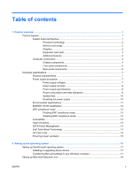
Boost Technology 14 HP Cool Tools ...14 Ensuring proper ventilation 15 2 Setting up the operating system ...16 Setting up the Microsoft operating system 17 Installing or upgrading device drivers 17 Transferring files and settings to your Windows computer 17 Setting up Red Hat Enterprise Linux - HP Z200 | HP Z200 SFF Workstation Maintenance and Service Guide - Page 6
the HP driver CD 18 Installing and customizing Red Hat-enabled computers 19 Verifying hardware compatibility 19 Setting up Novell SLED ...19 Updating the computer ...19 Updating the computer after first boot 19 Upgrading the BIOS ...19 Determining current BIOS 20 Upgrading BIOS 21 Upgrading - HP Z200 | HP Z200 SFF Workstation Maintenance and Service Guide - Page 7
ROM Flash ...46 Remote ROM Flash 46 HPQFlash ...46 FailSafe Boot Block ROM 47 Recovering the computer from Boot Block Recovery mode 47 Workstation security 57 Dual-state power button ...58 Changing the power button configuration 58 5 Replacing components ...59 Warnings and cautions ...60 Service - HP Z200 | HP Z200 SFF Workstation Maintenance and Service Guide - Page 8
bezel blanks 78 Locate system board drive connections 78 Locate extra guide screws 79 Carefully handle hard disk drives 80 Removing an optical the primary hard drive 88 Cable management ...93 Power connections 94 Using the Small Form Factor Computer in a Tower Orientation 95 Front panel I/O - HP Z200 | HP Z200 SFF Workstation Maintenance and Service Guide - Page 9
supply 101 Installing the power supply 102 System fan assembly ...103 Removing the system fan assembly 103 Installing the system fan assembly 104 Memory ...105 Supported DIMM configurations 105 DIMM installation guidelines 105 DIMM installation order 105 BIOS errors and warnings 106 Removing - HP Z200 | HP Z200 SFF Workstation Maintenance and Service Guide - Page 10
hard drive problems 137 Solving display problems 138 Solving audio problems 140 Solving printer problems 141 Self-troubleshooting with HP Vision Diagnostics 141 Overview ...142 Downloading and accessing HP Vision Diagnostics 144 Accessing HP Vision Diagnostics on the computer 145 Creating - HP Z200 | HP Z200 SFF Workstation Maintenance and Service Guide - Page 11
178 Cleaning the computer case ...178 Cleaning the keyboard ...178 Cleaning the monitor ...179 Cleaning the mouse ...179 Appendix D Locating HP resources ...180 Product information ...181 Product support ...182 Product documentation ...183 Product diagnostics ...184 Product updates ...185 Index - HP Z200 | HP Z200 SFF Workstation Maintenance and Service Guide - Page 12
xii ENWW - HP Z200 | HP Z200 SFF Workstation Maintenance and Service Guide - Page 13
chapter presents an overview of the hardware components of the computer. It includes these topics: Topics Product features on page 1 Computer specifications on page 7 Product features The following sections describe the computer system board architecture and components, and includes these topics - HP Z200 | HP Z200 SFF Workstation Maintenance and Service Guide - Page 14
connector, with four PCIe lanes connected. Processor technology This computer uses the Intel® Series 3450 chipset, including support of Quad Core Intel Xeon™ processors and processors of up to 95W. These processors incorporate an integrated 2-channel memory controller, microarchitecture improvements - HP Z200 | HP Z200 SFF Workstation Maintenance and Service Guide - Page 15
features The computer provides these additional features: ● Ten external and four internal USB 2.0 ports. ● A 240W power supply that is 89% efficient and permits Energy Star Version 5.0 system configurations. ● Supports European Union ERP Lot 6 power limit of less than 1W in off mode. ● HP Quiet Fan - HP Z200 | HP Z200 SFF Workstation Maintenance and Service Guide - Page 16
information on supported accessories and components for the computer, see http://partsurfer.hp.com. Chassis components The following image shows the components of a typical computer layout. Drive configurations can vary. Figure 1-2 Computer components Table 1-1 Computer component descriptions - HP Z200 | HP Z200 SFF Workstation Maintenance and Service Guide - Page 17
Table 1-2 Front panel connectors Item Symbol Description 1 Optical drive activity light 2 Optical drive 3 Optical drive manual eject button 4 Power button 5 USB 2.0 ports (4) Item 6 Symbol Description Microphone connector 7 Headphone connector 8 Hard drive activity light Optical - HP Z200 | HP Z200 SFF Workstation Maintenance and Service Guide - Page 18
Item Symbol Description 1 RJ-45 network connector 6 Display port (DP)1 2 Serial port 7 VGA (monitor)1 3 PS/2 mouse connector (green) 8 PS/2 keyboard connector (purple) 4 Power cord connector 5 USB 2.0 ports (6) 9 Audio line-out connector (green) 10 Audio line-in connector (blue - HP Z200 | HP Z200 SFF Workstation Maintenance and Service Guide - Page 19
89% efficient power supply to provide power for the computer. The power supply is compatible with ENERGY STAR Ver. 5 requirements. Power supply voltages Table 1-4 Power supply source voltages Source voltage Description +12 V-CPU Input to onboard regulator that supplies power to CPU +12 V-MAIN - HP Z200 | HP Z200 SFF Workstation Maintenance and Service Guide - Page 20
Nominal output voltage 12.1 12.1 Maximum continuous current 14A 12A 240W combined -12V -12.0 0.15A CAUTION: Do not exceed 240 watts of total continuous output power. Maximum combined current on +12V(CPU,Main) is 20A. 12Vsb 11.4 1.3A 8 Chapter 1 Product overview ENWW - HP Z200 | HP Z200 SFF Workstation Maintenance and Service Guide - Page 21
consumption and heat dissipation specifications are available for multiple configurations. To review available specifications, see http://www.hp.com/go/quickspecs. To reach zero power consumption, unplug the computer from the power outlet or use a power strip with an on/off switch. For additional - HP Z200 | HP Z200 SFF Workstation Maintenance and Service Guide - Page 22
what caused the overload and fix the problem. For troubleshooting information, see Diagnostics and troubleshooting on page 125. 3. Reconnect the power cord and restart the computer. When you power off the computer through the operating system, power consumption falls below what is considered low - HP Z200 | HP Z200 SFF Workstation Maintenance and Service Guide - Page 23
Environmental specifications The following table lists the environmental specifications of HP Workstations. Table 1-7 HP Workstation environmental specifications Temperature Operating: 5 to 35°C (40 to 95 500 Hz NOTE: Values do not indicate continuous vibration. ENWW Computer specifications 11 - HP Z200 | HP Z200 SFF Workstation Maintenance and Service Guide - Page 24
. Both the computer and monitor can be woken from sleep mode through user interaction with any of the computer input devices (mouse, keyboard, and so on). when configured with Wake On LAN (WOL) enabled, the computer can also be woken by a network signal. See the EPA ENERGY STAR Power Management Web - HP Z200 | HP Z200 SFF Workstation Maintenance and Service Guide - Page 25
Windows® 7, Windows Vista® Business, and Microsoft® Windows® XP Professional preinstalled are designed for accessibility. These products are tested with industry-leading Assistive Technology products. For more information see http://www.hp.com/accessibility. Hyper-threading This HP computer supports - HP Z200 | HP Z200 SFF Workstation Maintenance and Service Guide - Page 26
normal rate. When all CPU cores are not necessary for the workload, inactive cores are turned off and power is diverted to the active cores to increase their performance. Turbo Boost is enabled and disabled in computer BIOS. HP Cool Tools An HP computer with Windows XP includes additional software - HP Z200 | HP Z200 SFF Workstation Maintenance and Service Guide - Page 27
Ensuring proper ventilation Proper ventilation for the system is important for computer operation. Follow these guidelines to ensure adequate ventilation: ● Operate the computer on a sturdy, level surface. ● Place the computer in an area with adequate ventilation. Provide at least 15.24 CM (6 inches - HP Z200 | HP Z200 SFF Workstation Maintenance and Service Guide - Page 28
determine that you have the latest BIOS, drivers, and software updates installed on the computer. CAUTION: Do not add optional hardware or third-party devices to the HP computer until the operating system is successfully installed. Adding hardware might cause errors and prevent the operating system - HP Z200 | HP Z200 SFF Workstation Maintenance and Service Guide - Page 29
system must have the most recent updates, patches, and software fixes. For additional driver and software update information, refer to Upgrading device drivers on page 21. Transferring files and settings to your Windows computer The Microsoft Windows operating system offers data migration tools - HP Z200 | HP Z200 SFF Workstation Maintenance and Service Guide - Page 30
are currently available for download at http://www.hp.com/support/workstation_swdrivers. Installing with the HP driver CD To install the HP driver CD, see "Installing with the HP Installer Kit for Linux" in the HP Workstations for Linux manual at http://www.hp.com/support/workstation_manuals. 18 - HP Z200 | HP Z200 SFF Workstation Maintenance and Service Guide - Page 31
to work on HP Workstations visit http://www.hp.com/ support/linux_hardware_matrix. Setting up Novell SLED To set up the SUSE Linux Enterprise Desktop (SLED) on systems preloaded with the operating system: 1. Boot the computer. 2. Start the Installation Settings and enter the password, network - HP Z200 | HP Z200 SFF Workstation Maintenance and Service Guide - Page 32
Press F10 to enter the F10 Setup utility. The F10 Setup utility displays the computer BIOS version under File > System Information. 3. Note the computer BIOS version so that you can compare it with the BIOS versions that appear on the HP website. 20 Chapter 2 Setting up the operating system ENWW - HP Z200 | HP Z200 SFF Workstation Maintenance and Service Guide - Page 33
than the one on your system, download the appropriate version for the computer. Follow the instructions in the release notes to complete the installation. Upgrading device drivers If you install a peripheral device (such as a printer, display adapter, or network adapter), confirm you have the latest - HP Z200 | HP Z200 SFF Workstation Maintenance and Service Guide - Page 34
the HP Backup and Recovery Manager. ● RestorePlus! The RestorePlus! process reinstalls the Windows operating system and device drivers (for recovery point was made is saved. NOTE: HP Backup and Restore is only supported on the HP xw6600 and xw8600 Workstations. The Recovery Point is saved to the hard - HP Z200 | HP Z200 SFF Workstation Maintenance and Service Guide - Page 35
region see http://www.hp.com/ support/contactHP. Restoring Windows 7 or Windows Vista This section describes how to restore Windows 7 or Windows Vista. Ordering the RestorePlus! media If you ordered restore media with your computer, the media is included with your computer components. If you did - HP Z200 | HP Z200 SFF Workstation Maintenance and Service Guide - Page 36
! > Microsoft Windows XP operating system > Supplemental media. NOTE: Depending on the options, there might be additional DVDs you can create. 5. Follow the prompts to create RestorePlus!, operating system, and HPBR media. If you are unable to create CD/DVDs on your computer, call HP Support and - HP Z200 | HP Z200 SFF Workstation Maintenance and Service Guide - Page 37
Backup and Recovery (HPBR) media NOTE: HPBR is only supported on Windows XP systems. For details, refer to the documentation on the Supplemental Software - HP Backup and Recovery CD included with the computer. The documentation can be accessed during installation. The Initial Recovery Point can be - HP Z200 | HP Z200 SFF Workstation Maintenance and Service Guide - Page 38
that shipped with Windows XP includes a during the boot process is small. It comes about the time desktop. You can click this icon to go to the /iso directory. The /iso directory contains all iso images used to preload your computer. To recover or restore the original image, follow the instructions - HP Z200 | HP Z200 SFF Workstation Maintenance and Service Guide - Page 39
NOTE: Make copies of the ISO recovery images on CD as backup files in case your computer experiences a hard drive failure. ENWW Restoring Novell SLED 27 - HP Z200 | HP Z200 SFF Workstation Maintenance and Service Guide - Page 40
4 System management This section describes the tools and utilities that provide system management for the computer. It includes these topics: Topics BIOS ROM on page 29 The Computer Setup (F10) Utility on page 29 Desktop management on page 39 28 Chapter 4 System management ENWW - HP Z200 | HP Z200 SFF Workstation Maintenance and Service Guide - Page 41
as firmware in ROM. It includes functions such as Power on Self Test (POST), PCI device initialization, Plug and Play support, power management, and the Computer Setup (F10) Utility. The BIOS ROM is an 8MB Serial Peripheral Interface (SPI) port. See http://www.hp.com/go/quickspecs to review the - HP Z200 | HP Z200 SFF Workstation Maintenance and Service Guide - Page 42
ports, audio, or embedded NIC. Hidden devices are inaccessible, which increases system security. ● Enable or disable removable media boot ability. ● Enable or disable removable media write ability (if supported by hardware). ● Replicate the computer setup by saving system configuration information - HP Z200 | HP Z200 SFF Workstation Maintenance and Service Guide - Page 43
miss the opportunity to press F10. 3. Select the language from the list and press the Enter key. In the Computer Setup (F10) Utility menu, five headings are displayed: File, Storage, Security, Power, and Advanced. 4. Use the left and right arrow keys to select the appropriate heading, use the up and - HP Z200 | HP Z200 SFF Workstation Maintenance and Service Guide - Page 44
Displays system temperatures and fan speeds. Set Time and Date Enables you to set system time and date. Flash System ROM Enables you to upgrade the BIOS from a ROM image on diskette, CD, or USB. Replicated Setup Provides these options: ● Save to Removable Media-Saves the computer configuration - HP Z200 | HP Z200 SFF Workstation Maintenance and Service Guide - Page 45
Mode-Enables the BIOS to determine the translation mode used to configure a formatted SATA test option is not displayed in the setup menu. This selection appears only when at least one drive capable of performing the IDE DPS self-test is attached to the computer. By default, the SATA controller - HP Z200 | HP Z200 SFF Workstation Maintenance and Service Guide - Page 46
Embedded Ethernet controller ● Embedded Ethernet controller (ASF) Second embedded LAN. (Not available in some configurations.) computer setup options, to flash the ROM, and to make changes to certain Plug and Play settings under Windows. Power-On Password Enables you to set and enable the power - HP Z200 | HP Z200 SFF Workstation Maintenance and Service Guide - Page 47
the following devices available or hidden to the computer: ● Serial Port ● Front USB Ports ● Rear USB Ports ● Internal USB Ports ● System Audio ● IEEE 1394 Controller (Not available on some models.) ● Ethernet Controller ● Ethernet Controller (ASF) (Not available on some models.) ● Legacy Diskette - HP Z200 | HP Z200 SFF Workstation Maintenance and Service Guide - Page 48
. If this option is made available, the following options become available: ◦ Power-On Authentication Support-Enables and disables an authentication feature that requires you to enter a TPM user key password to start the computer. This feature uses the TPM to generate and store the authentication - HP Z200 | HP Z200 SFF Workstation Maintenance and Service Guide - Page 49
accesses the Setup screen. ● F12 Prompt (Displayed or Hidden)-Selecting Displayed displays F12=Network Service Boot during POST. Selecting Hidden prevents the text from being displayed but pressing F12 still forces the computer to attempt booting from the network. ● Option ROM1 prompt (Enable or - HP Z200 | HP Z200 SFF Workstation Maintenance and Service Guide - Page 50
options: ● Num Lock State at Power-On (On or Off) ● S5 Wake-on-LAN (Enable or Disable) ● Multiprocessor (Activates a single core.) ● Unique Sleep State Blink Rates (Enable or Disable) ● Internal speaker ● Monitor Tracking (Enable or Disable) ● NIC PXE Option ROM1 Download (Enable or Disable) ● SATA - HP Z200 | HP Z200 SFF Workstation Maintenance and Service Guide - Page 51
45 ROM Flash on page 46 FailSafe Boot Block ROM on page 47 Workstation security on page 48 Fault notification and recovery on page 57 Dual-state power button on page 58 NOTE: Support for specific features described in this guide can vary by model and software version. ENWW Desktop management 39 - HP Z200 | HP Z200 SFF Workstation Maintenance and Service Guide - Page 52
software, or drivers To initiate a remote system installation, press F12 when F12=Network Service Boot appears in the lower right corner of the HP logo screen. Follow the onscreen instructions to continue the installation process. The default boot order is a BIOS configuration setting that can - HP Z200 | HP Z200 SFF Workstation Maintenance and Service Guide - Page 53
you might see a keyboard error message. Disregard it. 3. Select File>Replicated Setup>Save to Removable Media. Follow the instructions on the screen to create the configuration diskette or USB media device. 4. Power off the computer you are configuring and insert the configuration diskette into the - HP Z200 | HP Z200 SFF Workstation Maintenance and Service Guide - Page 54
not copy the setup configuration from an HP xw8600 Workstation to an HP Z200 Workstation. This method takes longer to prepare the configuration diskette, but copying the configuration to target computers is fast. A bootable diskette is required for this procedure. If Windows XP is not available to - HP Z200 | HP Z200 SFF Workstation Maintenance and Service Guide - Page 55
device drivers and ROM BIOS ● Remote changing of boot order ● Configuration of system BIOS settings The HP Client Management Solutions (CMS), available for download from http://www.hp.com/go/ easydeploy, are standards-based solutions for managing and controlling computers in a networked environment - HP Z200 | HP Z200 SFF Workstation Maintenance and Service Guide - Page 56
to-use interface for locating and downloading software updates for the HP client PC models in your environment. By specifying your models, operating system, and language, you can quickly locate, sort, and select the softpaqs you need. To download HP SoftPaq Download Manager, visit http://h20331.www2 - HP Z200 | HP Z200 SFF Workstation Maintenance and Service Guide - Page 57
on Windows computers that enables you to update system-level software on multiple systems simultaneously. When executed on a PC client system, SSM detects hardware and software versions and then updates the software from a central repository, known as a file store. Driver versions supported by - HP Z200 | HP Z200 SFF Workstation Maintenance and Service Guide - Page 58
allows system administrators to safely upgrade the ROM on remote HP computers from a centralized network management console, resulting in a consistent deployment of, and greater control over, HP PC ROM images over the network. To use Remote ROM Flash, the computer must be powered on, or turned on - HP Z200 | HP Z200 SFF Workstation Maintenance and Service Guide - Page 59
Block ROM provides enough support to start the computer from a BIOS image CD created from a SoftPaq. The BIOS image CD programs the system ROM with a valid image. When Boot Block detects an invalid system ROM, the computer power LED blinks red eight times and the computer beeps eight times; then the - HP Z200 | HP Z200 SFF Workstation Maintenance and Service Guide - Page 60
the computer provide asset tracking data that can be managed using HP Systems Insight Manager (HP SIM), HP CMS, Control integrated serial, parallel, USB, or infrared interface From the Computer Setup (F10) Utility menu Power-On Password Prevents use of the computer until the From the Computer - HP Z200 | HP Z200 SFF Workstation Maintenance and Service Guide - Page 61
the password or access the data. DriveLock has been implemented as an extension to Computer Setup (F10) functions. It is only available when hard disk drives that support the ATA security command set are detected. On HP computers, it is not available when the SATA emulation mode is RAID+AHCI or RAID - HP Z200 | HP Z200 SFF Workstation Maintenance and Service Guide - Page 62
unauthorized software, other asset control functions, and support. For users with less stringent security requirements, HP does not recommend enabling DriveLock warm-start or restart from Windows, if neither attempt succeeds, POST halts and the user is instructed to cycle power. 50 Chapter 4 System - HP Z200 | HP Z200 SFF Workstation Maintenance and Service Guide - Page 63
user password: 1. Power on or restart the computer. 2. As soon as the computer is powered on, press and hold F10 until you enter the Computer Setup (F10) the computer, and then press and hold F10 again to access the utility. If you are using a PS2 keyboard, you might see a keyboard error message. - HP Z200 | HP Z200 SFF Workstation Maintenance and Service Guide - Page 64
time, you must restart the computer, and then press and hold F10 again to access the utility. If you are using a PS/2 keyboard, you might see a keyboard error message. Disregard it. 3. Select Security>Setup Password and then follow the onscreen instructions. 4. Before exiting, select File>Save - HP Z200 | HP Z200 SFF Workstation Maintenance and Service Guide - Page 65
keyboard error message. Disregard it. 3. Select Security>Power-On Password and then follow the onscreen instructions. 4. Before exiting, select File>Save Changes and Exit. Entering a power-on password To enter a power-on password: 1. Restart the computer. 2. When the key icon appears on the monitor - HP Z200 | HP Z200 SFF Workstation Maintenance and Service Guide - Page 66
press F10 at the appropriate time, you must restart the computer and press and hold F10 again to access the utility. If you are using a PS/2 keyboard, you might see a keyboard error message. Disregard it. 3. When the key icon appears on the monitor, enter the setup password, and press Enter. Type - HP Z200 | HP Z200 SFF Workstation Maintenance and Service Guide - Page 67
power-on or setup password: 1. Power on or restart the computer. 2. Choose from the following: ● To delete the power-on password, go to step 4. ● To delete the setup password, as soon as the computer is powered on, press and hold F10 until you enter the Computer Yugoslavia ENWW Desktop management - HP Z200 | HP Z200 SFF Workstation Maintenance and Service Guide - Page 68
the computer. For instructions about clearing passwords, see Configuring Computer Setup (F10) Utility. The solenoid lock FailSafe Key-available from HP-is is a device for manually disabling the solenoid lock. You will need the FailSafe Key in case of forgotten password, power loss, or computer - HP Z200 | HP Z200 SFF Workstation Maintenance and Service Guide - Page 69
DIMM, enabling you to take action before you experience noncorrectable memory errors. ECC DIMMs are standard on this computer. Thermal sensors Several thermal sensors in the HP Workstation regulate computer fans to maintain an acceptable, efficient chassis temperature. ENWW Desktop management 57 - HP Z200 | HP Z200 SFF Workstation Maintenance and Service Guide - Page 70
Control Panel>Power Options. 2. In Power Options Properties, select the Advanced tab. 3. In the Power Button section, select Hibernate. NOTE: Hibernate must be enabled in the Hibernate tab. After configuring the power button to function as a button, you can press the power button to put the computer - HP Z200 | HP Z200 SFF Workstation Maintenance and Service Guide - Page 71
5 Replacing components This chapter presents removal and installation procedures for most internal computer components. It includes these topics: Topics Warnings and cautions on page 60 Service considerations on page 61 Customer Self-Repair on page 65 Removing and installing components on page 66 - HP Z200 | HP Z200 SFF Workstation Maintenance and Service Guide - Page 72
a common ground for the equipment you are working on by connecting the static-free mat, static strap, and peripheral units to that piece of equipment. NOTE: HP accessories are for use in HP Workstation products. They have been extensively tested for reliability and are manufactured to high quality - HP Z200 | HP Z200 SFF Workstation Maintenance and Service Guide - Page 73
Service considerations Review the following service considerations before replacing system components. Cautions, warnings and safety precautions Review the cautions, warnings, and safety precautions before accessing the computer components. Also, review the Safety and Regulatory Guide that came - HP Z200 | HP Z200 SFF Workstation Maintenance and Service Guide - Page 74
, leads, or circuitry. ● Place reusable electrostatic-sensitive parts from assemblies in protective packaging or nonconductive foam. Personal connector on the grounding mat or computer. ● Heel straps, toe straps, and boot straps-These can be used at standing computers and are compatible with most - HP Z200 | HP Z200 SFF Workstation Maintenance and Service Guide - Page 75
parts, and assemblies by the case or PCB laminate. Handle them only in static-free work areas. ● Disconnect power and input signals before inserting and removing connectors or test Conductive foam ● Conductive tabletop computers with a ground cord of to ground ● Field service kits ● Static awareness - HP Z200 | HP Z200 SFF Workstation Maintenance and Service Guide - Page 76
driver ● Flat blade and cross-tip screwdrivers ● Diagnostics software Special handling of components The components included in this section require special handling when servicing the computer be caught or snagged by parts being removed or replaced. When servicing the computer, be sure that cables - HP Z200 | HP Z200 SFF Workstation Maintenance and Service Guide - Page 77
monitors or speakers. Lithium coin cell battery The battery included with the computer provides power to the real-time clock and has a lifetime of about three years. For instructions obtain replacement parts and install them on the computer. For more information, see http://www.hp.com/go/selfrepair - HP Z200 | HP Z200 SFF Workstation Maintenance and Service Guide - Page 78
32/33 11 Front power button/LED 21 Solenoid hood lock 2 Front system fan 12 Speaker 22 Audio 3 PCIe2 x16(16) 13 Front audio 23 Keyboard/mouse 4 PCIe x16(4) 14 Front USB 24 VGA/1st serial 5 PCIe x1 15 Front USB 25 Display port 6 CPU socket 16 SATA power 26 USB 7 Chassis intrusion - HP Z200 | HP Z200 SFF Workstation Maintenance and Service Guide - Page 79
For related system architecture information, see System board architecture on page 1. ENWW Removing and installing components 67 - HP Z200 | HP Z200 SFF Workstation Maintenance and Service Guide - Page 80
the following steps before servicing a computer: 1. Locate and clear a suitable work area. 2. Close all open software applications. 3. Remove all USB keys, diskettes, CDs, and DVDs from the computer. 4. Shut down the operating system. 5. Power off the computer and all peripheral devices connected - HP Z200 | HP Z200 SFF Workstation Maintenance and Service Guide - Page 81
, power button assembly, system fan, or system speaker Chassis lock Access panel Front bezel System board Chassis lock Access panel Airflow guide Expansion cards or DIMMs Heatsink Removing the cable lock (optional) If a cable lock is installed on the computer, remove it before servicing the - HP Z200 | HP Z200 SFF Workstation Maintenance and Service Guide - Page 82
Unlock it and pull it out of the cable lock slot as shown in the following figure. Figure 5-2 Removing the cable lock 70 Chapter 5 Replacing components ENWW - HP Z200 | HP Z200 SFF Workstation Maintenance and Service Guide - Page 83
the access panel. Removing the access panel WARNING! Power off the computer and disconnect the power cord from the electrical outlet before you remove the computer access panel. To remove the access panel: 1. Prepare the computer for servicing by following the Predisassembly procedures on page 68 - HP Z200 | HP Z200 SFF Workstation Maintenance and Service Guide - Page 84
describes how to remove and install the front chassis bezel. Removing the front bezel To remove the front bezel: 1. Prepare the computer for servicing by following the Predisassembly procedures on page 68. CAUTION: Failure to follow the predisassembly procedures can result in equipment damage or - HP Z200 | HP Z200 SFF Workstation Maintenance and Service Guide - Page 85
Front bezel security You can lock the front bezel in place by installing a security screw provided by HP. To install the security screw: 1. Prepare the computer for servicing by following the Predisassembly procedures on page 68. CAUTION: Failure to follow the predisassembly procedures can result in - HP Z200 | HP Z200 SFF Workstation Maintenance and Service Guide - Page 86
describes how to remove and install the sensor. Removing the access panel sensor To remove the access panel sensor: 1. Prepare the computer for servicing by following the Predisassembly procedures on page 68. CAUTION: Failure to follow the predisassembly procedures can result in equipment damage or - HP Z200 | HP Z200 SFF Workstation Maintenance and Service Guide - Page 87
3. Disconnect the sensor cable from the in-line chassis cable as shown below (1). Figure 5-7 Removing the access panel sensor 4. Slide the sensor back in its slot, push the sensor down, and then remove it from the chassis (2). Installing the access panel sensor To replace the access panel sensor, - HP Z200 | HP Z200 SFF Workstation Maintenance and Service Guide - Page 88
To remove the access panel solenoid lock: 1. Prepare the computer for servicing by following the Predisassembly procedures on page 68. CAUTION: and installing drives . This section describes how to remove and install the Z200 SFF drives: ● Optical disk drive ● Internal hard disk drive ● Optional - HP Z200 | HP Z200 SFF Workstation Maintenance and Service Guide - Page 89
optical drive shown) NOTE: The drive configuration on your computer may differ from the drives shown above. NOTE: You can install a maximum of two hard disk drives in the Z200 SFF. NOTE: For additional information about configuring SATA RAID devices, see Configuring RAID deviceson page 162. ENWW - HP Z200 | HP Z200 SFF Workstation Maintenance and Service Guide - Page 90
board drive connections Adding a new drive may require that you make new connections from the drive to the system board. Refer to the following illustration and table to identify the system board drive connectors. Figure 5-9 System board drive connections 78 Chapter 5 Replacing components ENWW - HP Z200 | HP Z200 SFF Workstation Maintenance and Service Guide - Page 91
does not support Parallel ATA (PATA) optical drives or PATA hard drives. Locate extra guide screws Each drive requires four guide screws to ensure the drive lines up correctly in the drive cage and locks in place. HP provides extra guide - HP Z200 | HP Z200 SFF Workstation Maintenance and Service Guide - Page 92
Screws Optical disk drives, SSDs, small form factor hard drives (6.3cm/2.5in), media card reader 2 Silver 6-32 Standard Screws 8.9cm/3.5in hard disk drives, front bezel security There are at total of five extra silver 6-32 standard screws. Four are used as guide screws for a secondary hard - HP Z200 | HP Z200 SFF Workstation Maintenance and Service Guide - Page 93
the drive cage to its upright position. Figure 5-11 Rotating the Drive Cage Up 5. Disconnect the power cable (1) and data cable (2) from the rear of the optical drive. Figure 5-12 Disconnecting the power and data cables 6. Rotate the drive cage back down to its normal position. CAUTION: Be careful - HP Z200 | HP Z200 SFF Workstation Maintenance and Service Guide - Page 94
drive from the drive cage (1). While pressing the drive retainer button, slide the drive back until it stops, then lift it up and out of the drive cage (2). Figure 5-13 Removing the optical drive 8. If you are replacing the drive, transfer the four guide screws from the old drive to the new one - HP Z200 | HP Z200 SFF Workstation Maintenance and Service Guide - Page 95
5. Install four M3 metric guide screws in the lower holes on each side of the drive. Either re-use the screws used by your previous optical drive or use the extra HP-provided guide screws mounted on the front of the chassis. (See Locate extra guide screws on page 79.) CAUTION: Use only 5-mm long - HP Z200 | HP Z200 SFF Workstation Maintenance and Service Guide - Page 96
or lowering it. One is located on the bottom side of the drive cage. The other is part of the chassis frame under the drive cage. Ensure that the data cable is routed through these guides before connecting it to the optical drive. Figure 5-17 Routing the drive cable 9. If necessary, route - HP Z200 | HP Z200 SFF Workstation Maintenance and Service Guide - Page 97
(1) and data cable (2) to the rear of the optical drive. Figure 5-18 Connecting the power and data cables 11. Carefully rotate the drive cage back down to its normal position. CAUTION: Be careful not to pinch any cables or wires - HP Z200 | HP Z200 SFF Workstation Maintenance and Service Guide - Page 98
drive, or, if you are removing a media card reader, disconnect the USB and 1394 cables from the system board as indicated in the following illustrations. Figure 5-19 Disconnecting the 1394 cable Figure 5-20 Disconnecting the Media Card Reader 1394 Cable NOTE: On some models, the media card reader - HP Z200 | HP Z200 SFF Workstation Maintenance and Service Guide - Page 99
the drive from the drive cage (1). While pressing the drive retainer button, slide the drive back until it stops, then lift it up and when rotating the drive cage down. 8. If you are replacing the drive, transfer the four guide screws from the old drive to the new one. 9. Replace the optical drive. - HP Z200 | HP Z200 SFF Workstation Maintenance and Service Guide - Page 100
computer until it locks into place. TIP: Angle the drive toward one side of the chassis to line up the guide Locate system board drive connections on page 78 for an illustration of the system board drive connectors. 7. Replace the hard drive is located under the power supply. To remove and replace the - HP Z200 | HP Z200 SFF Workstation Maintenance and Service Guide - Page 101
4. Rotate the drive cage to its upright position. Figure 5-23 Rotating the Drive Cage Up 5. Rotate the power supply to its upright position. The hard drive is located beneath the power supply. Figure 5-24 Rotating the power supply up ENWW Removing and installing components 89 - HP Z200 | HP Z200 SFF Workstation Maintenance and Service Guide - Page 102
6. Disconnect the power cable (1) and data cable (2) from the hard drive. Figure 5-25 Removing the optical drive 7. Press down on the green release latch next to the hard - HP Z200 | HP Z200 SFF Workstation Maintenance and Service Guide - Page 103
drive to the drive carrier (1). b. Use the black M3 screws from the front of the chassis to mount the small form factor drive to the carrier (2). (See Locate extra guide screws on page 79for screw location.) Figure 5-28 Attaching the drive to the carrier ENWW Removing and installing components 91 - HP Z200 | HP Z200 SFF Workstation Maintenance and Service Guide - Page 104
9. Align the guide screws with the slots on the chassis drive cage, press the hard drive down into the bay, then slide it back until it stops and locks in place. Figure 5-29 Installing the hard drive (drive carrier shown) 92 Chapter 5 Replacing components ENWW - HP Z200 | HP Z200 SFF Workstation Maintenance and Service Guide - Page 105
procedures on page 68. Cable management The Z200 Small Form Factor chassis is a very compact computer and proper routing of the internal cables is critical to the operation of the computer. Follow good cable management practices when working inside the computer ● Keep cables away from direct contact - HP Z200 | HP Z200 SFF Workstation Maintenance and Service Guide - Page 106
supply, or computer cover to push cables down into the chassis. Always position the cables to lay properly by themselves or in the cable guides and chassis areas designed for cable routing. When removing the power supply power cables from the connector on the system board, always follow these steps - HP Z200 | HP Z200 SFF Workstation Maintenance and Service Guide - Page 107
Item Description Item P3 CPU power P7 P4 Hard disk drive Description SATA PWR1 (P160 on system board) for optical disk or hard disk drives Using the Small Form Factor Computer in a Tower Orientation The Small Form Factor computer can be used in a tower orientation. The HP logo plate on the - HP Z200 | HP Z200 SFF Workstation Maintenance and Service Guide - Page 108
install a front panel I/O device assembly. Removing the front panel I/O device assembly To remove the front panel I/O device assembly: 1. Disconnect power from the computer (see Predisassembly procedures on page 68 ). 2. Remove the access panel (see Removing the access panel on page 71). 3. Remove - HP Z200 | HP Z200 SFF Workstation Maintenance and Service Guide - Page 109
front panel I/O device assembly cables from the system board as shown below. Figure 5-34 Disconnecting the front panel I/O cables 7. Carefully guide the cables through the chassis openings (1), as shown in the following figure. Figure 5-35 Removing the front panel I/O device assembly 8. Carefully - HP Z200 | HP Z200 SFF Workstation Maintenance and Service Guide - Page 110
the front panel I/O device assembly: 1. Prepare the computer for servicing by following the Predisassembly procedures on page 68. CAUTION its upright position. Figure 5-36 Rotating the Drive Cage Up 5. Carefully guide the front panel I/O device assembly cables through the chassis openings from which - HP Z200 | HP Z200 SFF Workstation Maintenance and Service Guide - Page 111
7. Connect the front panel USB (1 and 2), front audio (3), and front power/LED (4) cables to the system board as shown in the following diagram. Figure 5-37 Connecting the front panel I/O device cables 8. Rotate the drive cage down - HP Z200 | HP Z200 SFF Workstation Maintenance and Service Guide - Page 112
Speaker This section describes how to remove and install the speaker. Removing the speaker To remove the speaker: 1. Prepare the computer for servicing by following the Predisassembly procedures on page 68. CAUTION: Failure to follow the predisassembly procedures can result in equipment damage or - HP Z200 | HP Z200 SFF Workstation Maintenance and Service Guide - Page 113
supply This section describes how to remove and install a power supply. Removing the power supply To remove the power supply: 1. Prepare the computer for servicing by following the Predisassembly procedures on page 68. CAUTION: Failure to follow the predisassembly procedures can result in equipment - HP Z200 | HP Z200 SFF Workstation Maintenance and Service Guide - Page 114
5. Slide the power supply toward the chassis and then up to remove it from the chassis. Figure 5-40 Removing power supply Installing the power supply To install the power supply, reverse the previous steps. 102 Chapter 5 Replacing components ENWW - HP Z200 | HP Z200 SFF Workstation Maintenance and Service Guide - Page 115
To remove the system fan assembly: 1. Prepare the computer for servicing by following the Predisassembly procedures on page 68. CAUTION bezel on page 72). 4. Remove the cables from the support arm on the airflow guide 5. Remove the airflow guide by pulling it straight up and out of the chassis, - HP Z200 | HP Z200 SFF Workstation Maintenance and Service Guide - Page 116
cable from the system board as shown in the following figure. Figure 5-42 Disconnecting fan wires 7. Remove the fan assembly by pushing in on the four release tabs on the front of the chassis (1), and then sliding the fan assembly into the chassis until you can lift it out. Figure 5-43 - HP Z200 | HP Z200 SFF Workstation Maintenance and Service Guide - Page 117
configurations The computer supports these DIMM configurations: ● Four DIMM slots ● Memory configuration from 1 GB to 16GB ● No support for mirroring ● No support for DIMM sparing ● Error checking and correcting (ECC) and non-ECC DIMMs are supported. DIMM installation guidelines ● Install only HP - HP Z200 | HP Z200 SFF Workstation Maintenance and Service Guide - Page 118
computer can still be started. The warning will indicate the location of the failed DIMM on the system board or memory riser. ● If there is no way for the BIOS to obtain a valid memory configuration by disabling plugged-in memory, the BIOS halts with a diagnostics code for memory error (five beeps - HP Z200 | HP Z200 SFF Workstation Maintenance and Service Guide - Page 119
Removing a DIMM To remove a DIMM: 1. Prepare the computer for servicing by following the Predisassembly procedures on page 68. CAUTION: Failure to follow the predisassembly procedures can result in equipment damage or data loss. 2. Remove the - HP Z200 | HP Z200 SFF Workstation Maintenance and Service Guide - Page 120
Installing a DIMM To install the DIMM: 1. Prepare the computer for servicing by following the Predisassembly procedures on page 68. CAUTION: Failure to follow the predisassembly procedures can result in equipment damage or data loss. 2. Remove the - HP Z200 | HP Z200 SFF Workstation Maintenance and Service Guide - Page 121
keyed for proper installation. To prevent socket or DIMM damage, align these guides properly when installing DIMMs. Figure 5-48 Opening DIMM socket levers 6. Secure the socket levers (2). 7. Rotate the drive cage and the power supply down to their normal positions. 8. Replace the front bezel (see - HP Z200 | HP Z200 SFF Workstation Maintenance and Service Guide - Page 122
connector, with four PCIe lanes connected. Card configuration restrictions for power supplies CAUTION: To prevent damage, the overall power consumption of the computer (including I/O cards, CPU, and memory) must not exceed the maximum rating of the computer power supply. For power supply information - HP Z200 | HP Z200 SFF Workstation Maintenance and Service Guide - Page 123
use this slot for the graphics card, only cards certified as After Market Options are supported. ● Insert a second graphics card in the white PCIe x16 slot. ● Install slot, and an x4 card in a an x1 slot. ● An x1 connector supports an x1 card only. Although, an x1 card can be inserted into any slot, - HP Z200 | HP Z200 SFF Workstation Maintenance and Service Guide - Page 124
I/O slots can support other PCIe cards four PCIe lanes connected. Use the following table to determine PCIe card compatibility. Table 5-9 Computer expansion card To remove an expansion card: 1. Prepare the computer for servicing by following the Predisassembly procedures on page 68. CAUTION: Failure - HP Z200 | HP Z200 SFF Workstation Maintenance and Service Guide - Page 125
4. Push down on the expansion card retention clamp levers on the inside of the chassis to open the retention clamp (1) as shown below. Figure 5-50 Releasing the retention clamp 5. If the card slot has a latch, release the latch (1), and then carefully lift the card from the chassis (2). Figure 5-51 - HP Z200 | HP Z200 SFF Workstation Maintenance and Service Guide - Page 126
card Visit http://www.hp.com/go/quickspecs to learn which graphics cards are supported in the computer, how much memory each graphics card includes, and graphics card power requirements. To install an expansion card: 1. Prepare the computer for servicing by following the Predisassembly procedures - HP Z200 | HP Z200 SFF Workstation Maintenance and Service Guide - Page 127
Removing the slot cover 5. Angle the expansion card to Insert it into the expansion card guide. 6. Align the PCIe card keyway with the slot key, and then firmly seat the card by the card, connect the auxiliary power cable to the card (not illustrated). ENWW Removing and installing components 115 - HP Z200 | HP Z200 SFF Workstation Maintenance and Service Guide - Page 128
8. Replace the access panel (see Installing the access panel on page 71). 9. Restore all connections and equipment that you removed during the Predisassembly procedures on page 68. 116 Chapter 5 Replacing components ENWW - HP Z200 | HP Z200 SFF Workstation Maintenance and Service Guide - Page 129
that comes with the computer provides power to the real-time clock and has a minimum lifetime of about three years. WARNING! This computer includes a lithium battery. battery To remove the battery: 1. Prepare the computer for servicing by following the Predisassembly procedures on page 68. CAUTION - HP Z200 | HP Z200 SFF Workstation Maintenance and Service Guide - Page 130
CPU heatsink This section describes how to remove and install a CPU heatsink. Removing the CPU heatsink To remove a heatsink: 1. Prepare the computer for servicing 3. Remove the airflow guide. 4. Slowly and evenly loosen one pair of diagonally opposite screws (1) from the CPU until the screw shanks - HP Z200 | HP Z200 SFF Workstation Maintenance and Service Guide - Page 131
cloth to clean the thermal interface residue from the CPU and the heatsink. Let the alcohol on the CPU and CPU heatsink dry completely. Installing the CPU heatsink To install a heatsink: 1. Prepare the computer for servicing by following the Predisassembly procedures on page 68. CAUTION: Failure - HP Z200 | HP Z200 SFF Workstation Maintenance and Service Guide - Page 132
CAUTION: Do not overtighten the heatsink screws. Overtightening can strip the threads in the chassis. 9. Replace the airflow guide. 10. Replace the access panel (see Installing the access panel on page 71). 11. Restore all connections and equipment that you removed during the Predisassembly - HP Z200 | HP Z200 SFF Workstation Maintenance and Service Guide - Page 133
This section describes how to remove and install a CPU. Removing a CPU To remove a CPU: 1. Prepare the computer for servicing by following the Predisassembly procedures on page 68. CAUTION: Failure to follow the predisassembly procedures can result in equipment damage or data loss. 2. Remove the - HP Z200 | HP Z200 SFF Workstation Maintenance and Service Guide - Page 134
a CPU: 1. Prepare the computer for servicing by following the Predisassembly procedures on page 68. CAUTION: Failure to follow the predisassembly procedures can result in equipment damage or data loss. 2. Remove the access panel (see Removing the access panel on page 71). 3. Remove the airflow guide - HP Z200 | HP Z200 SFF Workstation Maintenance and Service Guide - Page 135
board To remove the system board: 1. Prepare the computer for servicing by following the Predisassembly procedures on page 68. Power supply on page 101). 5. Remove expansion boards and graphics cards (see Removing an expansion card on page 112). 6. Remove the CPU heatsink (see Removing the CPU - HP Z200 | HP Z200 SFF Workstation Maintenance and Service Guide - Page 136
Product recycling HP encourages customers to recycle used electronic hardware, HP original print cartridges, and rechargeable batteries. For information about recycling HP components or products, see http://www.hp.com/go/recycle. 124 Chapter 5 Replacing components ENWW - HP Z200 | HP Z200 SFF Workstation Maintenance and Service Guide - Page 137
on page 127 Diagnosis guidelines on page 128 Troubleshooting checklist on page 130 HP troubleshooting resources and tools on page 131 Troubleshooting scenarios and solutions on page 134 Self-troubleshooting with HP Vision Diagnostics on page 141 Diagnostic codes and errors on page 152 ENWW 125 - HP Z200 | HP Z200 SFF Workstation Maintenance and Service Guide - Page 138
phone numbers, visit http://www.hp.com/support, select your region, and click Contact HP in the upper-left corner. Locating ID labels To assist in troubleshooting, product, serial, and authentication numbers are available on each computer. Typically each HP Workstation has two unique serial number - HP Z200 | HP Z200 SFF Workstation Maintenance and Service Guide - Page 139
base warranty information, see http://www.hp.com/support/warranty-lookuptool. To locate an existing Care Pack, see http://www.hp.com/go/lookuptool. To extend a standard product warranty, visit http://www.hp.com/hps/carepack. HP Care Pack Services offer upgraded service levels to extend and expand - HP Z200 | HP Z200 SFF Workstation Maintenance and Service Guide - Page 140
primary display adapter. During startup, the other monitor connectors are disabled; if the monitor is connected to one of these ports, it will not function after Power-on Self Test (POST). You can select the default source in Computer Setup (F10). 128 Chapter 6 Diagnostics and troubleshooting ENWW - HP Z200 | HP Z200 SFF Workstation Maintenance and Service Guide - Page 141
a different video port on the computer if one is available. Alternatively, replace the monitor with a monitor that you know is working properly. ● Upgrade the BIOS. A new release of the BIOS might have been released that supports new features or fixes your problem. ENWW Diagnosis guidelines 129 - HP Z200 | HP Z200 SFF Workstation Maintenance and Service Guide - Page 142
Troubleshooting checklist Before running diagnostic utilities, use the following checklist to find possible solutions for computer or software problems. ● Is the computer and monitor connected to a working electrical outlet? ● Is the computer powered on? ● Is the blue power light illuminated? ● Is - HP Z200 | HP Z200 SFF Workstation Maintenance and Service Guide - Page 143
NOTE: Currently, HP Help and Support Center does not work on Windows 7 or Windows Vista. E-support Online access and support resources include Web-based troubleshooting tools, technical knowledge databases, driver and patch downloads, online communities, and product change notification services. The - HP Z200 | HP Z200 SFF Workstation Maintenance and Service Guide - Page 144
appropriate to the workstation series and model, and to the problem you are troubleshooting. Instant Support and Active Chat HP Instant Support is a set of Web-based support tools that automate and speed up the resolution of desktop computing, tape storage, and printing problems. Active Chat enables - HP Z200 | HP Z200 SFF Workstation Maintenance and Service Guide - Page 145
port on the workstation if one is available. Alternatively, replace the monitor with a monitor that you know is working properly. ● Upgrade the BIOS. A new release of the BIOS might have been released that supports new features or fixes your problem. ENWW HP troubleshooting resources and tools - HP Z200 | HP Z200 SFF Workstation Maintenance and Service Guide - Page 146
HP Workstations for Linux User Manual at http://www.hp.com/support/linux_user_manual. Solving minor problems Table 6-1 Minor problems Problem Cause Possible Solution Workstation appears frozen Software control of the power and does not shut down when switch is not functional. the power button - HP Z200 | HP Z200 SFF Workstation Maintenance and Service Guide - Page 147
Table 6-1 Minor problems (continued) Problem Cause Workstation powered off automatically and the Power LED flashes red 2 times (once every second), followed by a 2second pause, and then two simultaneous beeps sounded. Processor thermal protection is activated. A fan might be blocked or not - HP Z200 | HP Z200 SFF Workstation Maintenance and Service Guide - Page 148
Error-checking, select Check Now. Diskette is incorrectly inserted. Remove and reinsert diskette. Files on the diskette are damaged. Verify the program diskettes. Drive cable is not properly connected. Reconnect the power cable and verify that all four -control is enabled. Use the Computer - HP Z200 | HP Z200 SFF Workstation Maintenance and Service Guide - Page 149
When drive activity stops, remove the diskette and press the Spacebar. The computer attempts to boot from the next device in the boot order. Diskette error has occurred. Restart the computer by pressing the power button. Cannot boot to diskette Diskette is not bootable. Replace with a bootable - HP Z200 | HP Z200 SFF Workstation Maintenance and Service Guide - Page 150
by 8 beeps). Fixed-sync monitor does not sync at the resolution specified. Verify that the monitor can accept the same horizontal scan rate as the resolution specified. Computer is in Hibernate mode. Press the power button to resume from Hibernate mode. Workstation monitor settings are - HP Z200 | HP Z200 SFF Workstation Maintenance and Service Guide - Page 151
match those supported by your graphics card and monitor. 3. Refer to your operating system and graphics card documentation for information about changing display settings. Power LED flashes red 6 times (once every second), followed by a 2-second pause, and then the computer beeps 6 times. Prevideo - HP Z200 | HP Z200 SFF Workstation Maintenance and Service Guide - Page 152
. Volume is muted. 1. From the Control Panel, select Sound, Speech and Audio Devices, and then select Sounds and Audio Devices. 2. Deselect the Mute checkbox. Computer is in Standby mode. Press the power button to resume from Standby mode. 140 Chapter 6 Diagnostics and troubleshooting ENWW - HP Z200 | HP Z200 SFF Workstation Maintenance and Service Guide - Page 153
tool that can be used by the end user or technical support personnel to view information about the hardware configuration of the computer and perform hardware troubleshooting on HP Desktop and Workstation systems. This diagnostic tool should be used to help determine hardware failures. Accessible by - HP Z200 | HP Z200 SFF Workstation Maintenance and Service Guide - Page 154
will be run on supported products when attempting to troubleshoot system issues. Overview The HP Vision Diagnostics utility allows you to view information about the hardware configuration of the computer and perform hardware diagnostic tests on the subsystems of the computer. The utility simplifies - HP Z200 | HP Z200 SFF Workstation Maintenance and Service Guide - Page 155
new device. You should run tests, save the test results, and print them so that you have printed reports available before placing a call to the Customer Support Center. NOTE: Third-party devices may not be detected by HP Vision Diagnostics. ENWW Self-troubleshooting with HP Vision Diagnostics 143 - HP Z200 | HP Z200 SFF Workstation Maintenance and Service Guide - Page 156
these steps to download the HP Vision Diagnostics utility from the HP Web site to a DVD or USB, and then use it to perform diagnostics on the computer: 1. Go to http://www.hp.com. 2. Select the Support & Drivers link. 3. Select the Download driver and software radio button. 4. Enter your product - HP Z200 | HP Z200 SFF Workstation Maintenance and Service Guide - Page 157
DVD and initiate the HP Vision Diagnostics utility. 5. Follow the HP Vision Diagnostic prompts to troubleshoot the computer. Using the HP Memory Test utility This section describes how to access the HP Memory Test utility. NOTE: The HP Memory Test is a comprehensive memory diagnostic utility that is - HP Z200 | HP Z200 SFF Workstation Maintenance and Service Guide - Page 158
are also some common operations that are part of the utility. They include: ● Exit Diagnostics button - This button will close HP Vision Diagnostic application and reboot your system. Any running test will be aborted. ● Reload button - If available, this button will rescan your system hardware and - HP Z200 | HP Z200 SFF Workstation Maintenance and Service Guide - Page 159
. ● Storage - Shows mass storage devices such as floppy drives, optical drives, SATA, SAS hard disk drives and controllers, as well as any RAID arrays. ● System - Shows information about system board devices such as fans and cables. ENWW Self-troubleshooting with HP Vision Diagnostics 147 - HP Z200 | HP Z200 SFF Workstation Maintenance and Service Guide - Page 160
during tests. NOTE: Memory can not be tested from within the HP Vision Diagnostics application. To test the memory in your computer, exit HP Vision Diagnostic, boot to either the CD or USB flash drive and select HP Memory Test from the boot menu. The Duration of Test options control the duration - HP Z200 | HP Z200 SFF Workstation Maintenance and Service Guide - Page 161
automatically displayed during the testing process. When the tests are complete, the Status tab shows whether the devices passed or failed. 6. If errors are found, go to the Errors tab to display detailed information and recommended actions. ENWW Self-troubleshooting with HP Vision Diagnostics 149 - HP Z200 | HP Z200 SFF Workstation Maintenance and Service Guide - Page 162
to either floppy or USB flash drive by clicking the Save button. Errors tab The Errors tab displays detailed information about any errors found, as well as any recommended actions. The Error Log displays the tests for devices that have failed during the diagnostic testing and includes the following - HP Z200 | HP Z200 SFF Workstation Maintenance and Service Guide - Page 163
may appear in the Errors tab. ● The Memory test tab section provides information on the HP Memory Test application that may be launched from the boot menu. ● The HP Support section provides information on obtaining technical support from HP. ENWW Self-troubleshooting with HP Vision Diagnostics 151 - HP Z200 | HP Z200 SFF Workstation Maintenance and Service Guide - Page 164
to remove the USB flash drive or CD from the optical drive. Diagnostic codes and errors This section presents information about diagnostic LED codes, LED color definitions, and POST error messages to help you troubleshoot problems. Diagnostic LED and audible (beep) codes This section describes - HP Z200 | HP Z200 SFF Workstation Maintenance and Service Guide - Page 165
-party memory with HP memory. 4. The problem might be on the system board. Contact HP for assistance. Red Power LED blinks six times, once every second, followed by a two-second pause. Six beeps. Pre-video graphics error. CAUTION: Internal components might be powered even when the computer is - HP Z200 | HP Z200 SFF Workstation Maintenance and Service Guide - Page 166
to the Maintenance and Service Guide for the computer model for detailed information on clearing CMOS. 2. The problem might be on the system board. Contact HP for assistance. Red Power LED blinks eight times, once every second, followed by a two-second pause. Eight beeps. Invalid ROM based on - HP Z200 | HP Z200 SFF Workstation Maintenance and Service Guide - Page 167
LED state LED color System status Solid Blue System is on. Flashing Blue System is in Standby. Solid or flashing Red System has experienced an error. (See POST error messages on page 156.) None No light System is in Hibernate, or is off. ENWW Diagnostic codes and errors 155 - HP Z200 | HP Z200 SFF Workstation Maintenance and Service Guide - Page 168
error messages The Power-On Self Text (POST) is a series of diagnostic tests that runs automatically when the computer is powered on. Audible and visual messages occur before the operating system starts if the POST encounters a problem. POST checks the following items to ensure that the computer - HP Z200 | HP Z200 SFF Workstation Maintenance and Service Guide - Page 169
Error RAM failure. 202-Memory Type Mismatch Memory modules do not match. Recommended action 1. Run the Computer Setup (F10) Utility or the Windows utilities. 2. Verify that the memory modules are installed properly. 3. If third-party memory has been added, test the memory configuration using HP - HP Z200 | HP Z200 SFF Workstation Maintenance and Service Guide - Page 170
the computer supports. 2. Remove the excess memory. 301-Keyboard Error Keyboard failure. 1. Reconnect the keyboard with the computer powered off. 2. Check the connector for bent or missing pins. 3. Be sure that none of the keys are pressed. 4. Replace the keyboard. 303-Keyboard Controller Error - HP Z200 | HP Z200 SFF Workstation Maintenance and Service Guide - Page 171
insufficient for hardware configuration Computer configuration requires more 1. power than the power supply can provide. 2. Reduce the computer power consumption. Replace the power supply with a high output power supply. 601-Diskette Controller Error Diskette controller circuitry or diskette - HP Z200 | HP Z200 SFF Workstation Maintenance and Service Guide - Page 172
device is connected and working properly. 924-Fatal error on IOH core X Fatal error detected on IOH core x, where x is 0 or 1. This type of error is identified on the line following. Potential system board problem; contact HP Support. 925-Fatal error on IOH miscellaneous Fatal miscellaneous - HP Z200 | HP Z200 SFF Workstation Maintenance and Service Guide - Page 173
the support provided by the processor Change the BIOS settings or upgrade the processor. 1804-A processor feature A processor feature is incompatible and the memory configuration with the memory configuration. are incompatible Restore the previous memory configuration. ERROR: Invalid 1394 GUID - HP Z200 | HP Z200 SFF Workstation Maintenance and Service Guide - Page 174
computer-specific maximum number of hard drives as discussed the sections below. Table 7-1 Maximum hard drives Workstation SATA hard drive SATA SFF* hard drive Z800 5 6 Z600 3 4 Z400 4 4 Z200 3 0 Z200 SFF 2 2 * Small form factor hard drive 162 Chapter 7 Configuring RAID - HP Z200 | HP Z200 SFF Workstation Maintenance and Service Guide - Page 175
. This BIOS is only used to support serial-attached optical drives. This section does not apply to configuring SATA RAID in the Linux environment. For Linux SATA RAID, refer to the Software RAID in Linux Workstations section in the HP Workstations for Linux User Guide at http://www.hp.com/support - HP Z200 | HP Z200 SFF Workstation Maintenance and Service Guide - Page 176
Configuring system BIOS Configure the system BIOS to enable embedded SATA RAID functionality. 1. To enter the system BIOS F10. 7. Use the arrows to highlight Advanced>Power-On Options, and then press Enter. 8. Use arrow key to highlight SATA RAID Option ROM Download, and then press Enter. 13. Use - HP Z200 | HP Z200 SFF Workstation Maintenance and Service Guide - Page 177
Configuration utility. 1. To enter the Intel Rapid Storage Manager option ROM Configuration utility, press Ctrl+l when prompted. 2. If required, refer the computer Maintenance and Service Guide installed (for workstations that support three or more hard drives): a. Press Enter to display the Select - HP Z200 | HP Z200 SFF Workstation Maintenance and Service Guide - Page 178
● Resetting the password jumper on page 167 ● Clearing and Resetting the CMOS on page 167 Preparing to configure passwords The Computer Setup (F10) Utility enables you to create setup and power-on passwords. There are three possibilities for setting passwords: ● Define a setup password only ● Define - HP Z200 | HP Z200 SFF Workstation Maintenance and Service Guide - Page 179
equipment. 9. Reconnect AC power to the computer. 10. Power on the computer. 11. Wait for the workstation to display the HP splash screen. 12. Repeat computer stores password information and information about the computer configuration. Using the CMOS Button To clear CMOS using the Clear CMOS button - HP Z200 | HP Z200 SFF Workstation Maintenance and Service Guide - Page 180
disconnect the computer power cord and external devices from power outlets. 2. Disconnect the keyboard, monitor, and other external devices that are connected to the computer. 3. Remove the access panel. CAUTION: Before pressing the Clear CMOS button, back up your computer CMOS settings. Pressing - HP Z200 | HP Z200 SFF Workstation Maintenance and Service Guide - Page 181
5. Select File->Apply Defaults and Exit, and then press F10 to accept. 6. Reset the computer passwords and configuration information, such as the system date and time. NOTE: This step does not clear the passwords. ENWW Clearing and Resetting the CMOS 169 - HP Z200 | HP Z200 SFF Workstation Maintenance and Service Guide - Page 182
A Connector pins Keyboard Mouse RJ-45 Ethernet Pin Signal 1 Data 2 Unused 3 Ground 4 +5 VDC 5 Clock 6 Unused Pin Signal 1 Data 2 Unused 3 Ground 4 +5 VDC 5 Clock 6 Unused Pin 10/100-MbSignal 1000-Mb signal 1 (+) Transmit Data - HP Z200 | HP Z200 SFF Workstation Maintenance and Service Guide - Page 183
cable, 6.35 MM (1/8 inch) SATA drive Pin Signal 1 +5 VDC 2 - Data 3 + Data 4 Ground Pin Signal 1 (Tip) 2 (Ring) 3 (Shield) Audio Power Ground Pin Signal 1 (Tip) 2 (Ring) 3 (Shield) Audio_Left Audio_Right Ground Pin Signal 1 (Tip) 2 (Ring) 3 (Shield) Audio_In_Left Audio_In_Right Ground - HP Z200 | HP Z200 SFF Workstation Maintenance and Service Guide - Page 184
P13 12V power P14 12V power P15 12V power VGA Pin Signal 1 Red Analog 2 Green Analog 3 Blue Analog 4 Monitor ID 5 GND Pin Signal 6 GND 7 GND 8 GND 9 +5 VDC 10 GND Pin Signal 11 Monitor ID 12 DDC Serial Data 13 Horizontal Sync 14 Vertical Sync 15 DDC Serial Clock Display port 172 - HP Z200 | HP Z200 SFF Workstation Maintenance and Service Guide - Page 185
Display port Pin Signal 1 ML_Lane 0(p) 2 GND 3 ML_Lane 0(n) 4 ML_Lane 1(p) 5 GND 6 ML_Lane 1(n) 7 ML_Lane 2(p) 8 GND 9 ML_Lane 2(n) 10 ML_Lane 3(p) Main power cable, P1 46 Pin Signal 11 GND 12 ML_Lane 3(n) 13 GND 14 GND 15 AUX CH(p) 16 GND 17 AUX CH(n) 18 Hot Plug Detect - HP Z200 | HP Z200 SFF Workstation Maintenance and Service Guide - Page 186
cable connects to the system board. These two cables have different pin counts and different colors. The PCIe power cable has a 6-pin black connector, and the CPU power cable has an 4-pin white connector. To see a picture of the PCIe cable and where it must be connected, see Removing and installing - HP Z200 | HP Z200 SFF Workstation Maintenance and Service Guide - Page 187
Internal USB 2 2x5 Pin Signal 1 +5V 2 +5V 3 USB7# 4 USB8# CAUTION: Possible equipment damage. 5 The 2x5 connector can be mated to either 6 a wide 2x5 option cable connector or a narrow 1x5 option cable connector. 7 To prevent damage to the connectors, 8 always connect a narrow 1x5 - HP Z200 | HP Z200 SFF Workstation Maintenance and Service Guide - Page 188
stacked over VGA port Display port connector Mouse connector stacked over keyboard connector Audio line in stacked over audio line out Clear CMOS switch/push button Power supply, 6-pin (white) Power command, 6-pin (white) Power supply, 4-pin (white) Front power button/LED (black) Internal speaker - HP Z200 | HP Z200 SFF Workstation Maintenance and Service Guide - Page 189
Designator P160 XBT1 XMM1 - XMM4 XU1 Silk screen SATAPWR1 XBT1 BAT XMM1 - XMM4 DIMM1 - DIMM4 XU1 Component/Description HDD power (black) Battery holder Memory slots Primary CPU socket ENWW 177 - HP Z200 | HP Z200 SFF Workstation Maintenance and Service Guide - Page 190
cleaning the keyboard, mouse, or air vents. ● Always disconnect the keyboard before cleaning it. ● Wear safety glasses equipped with side shields when cleaning the keyboard. Cleaning the computer case ● Follow the safety precautions presented in the Service Considerations section before cleaning - HP Z200 | HP Z200 SFF Workstation Maintenance and Service Guide - Page 191
. Never use solvents or flammable liquids on the monitor because display or housing damage may result. Cleaning the mouse 1. Follow the safety precautions presented in the Service Considerations section before cleaning the computer. 2. Remove the mouse ball from the housing by removing the retaining - HP Z200 | HP Z200 SFF Workstation Maintenance and Service Guide - Page 192
notifications ● QuickSpecs ● Customer Advisories, Security Bulletins, Notices Product diagnostics on page 184 ● Diagnostics tools ● Audible beeps and LED code definitions Product updates on page 185 ● Software, BIOS, and driver updates ● Operating system 180 Appendix D Locating HP resources ENWW - HP Z200 | HP Z200 SFF Workstation Maintenance and Service Guide - Page 193
HP Cool Tools icon on the desktop, or ● Open the HP Cool Tools folder by selecting Start > All Programs > HP Cool Tools. To learn more about these applications, click HP in the Maintenance and Service Guide on the Web at www.hp.com/go/bizsupport under the link for Manuals. Serial number and - HP Z200 | HP Z200 SFF Workstation Maintenance and Service Guide - Page 194
knowledge databases, driver and patch downloads, online communities, and proactive notification services. The following communication and diagnostic tools are also available: ● Instant Chat ● Instant Support ● Diagnose Problem Refer to the computer Maintenance and Service Guide for more information - HP Z200 | HP Z200 SFF Workstation Maintenance and Service Guide - Page 195
http://www.hp.com/go/bizsupport/. Workstation QuickSpecs The Product Bulletin contains QuickSpecs for HP Workstations. QuickSpecs provide an overall specification review of your product. It includes information about its features including the operating system, power supply, memory, CPU, and many - HP Z200 | HP Z200 SFF Workstation Maintenance and Service Guide - Page 196
The HP Vision Diagnostics utility can be downloaded from the HP Web site. To use this utility, refer to the appropriate section of the computer Maintenance and Service Guide. Audible beep and LED code definitions Refer to the appropriate section of the computer Maintenance and Service Guide for - HP Z200 | HP Z200 SFF Workstation Maintenance and Service Guide - Page 197
Product updates Table D-5 Product updates Topic Location Software, BIOS, and driver updates See http://www.hp.com/go/bizsupport to verify that you have the latest drivers for the computer. To locate the current computer BIOS on your Microsoft Windows computer, select Start>Help and Support>Pick - HP Z200 | HP Z200 SFF Workstation Maintenance and Service Guide - Page 198
39 Updating software 39 Workstation security 39 Diagnostic codes and errors LED and beep codes 129 LED colors 154 POST errors 155 Diagnostics and troubleshooting Diagnosis guidelines 125 HP Vision Diagnostics 125 Locating ID labels 125 Locating warranty info 125 Drivers Installing 17 Updating 17 - HP Z200 | HP Z200 SFF Workstation Maintenance and Service Guide - Page 199
Software Ordering 22 Support Locating HP resources iii U Updating the computer First boot update 19 Updating drivers 17 Updating the BIOS 21 W Windows 7 16 Windows operating system monitor 134 Windows Vista Restoring 22 Setting up 16 Windows XP Restoring 22 Setting up 16 Workstation setup Ensuring
-
 1
1 -
 2
2 -
 3
3 -
 4
4 -
 5
5 -
 6
6 -
 7
7 -
8
-
9
-
10
-
11
-
12
-
13
-
14
-
15
-
16
-
17
-
18
-
19
-
20
-
21
-
22
-
23
-
24
-
25
-
26
-
27
-
28
-
29
-
30
-
31
-
32
-
33
-
34
-
35
-
36
-
37
-
38
-
39
-
40
-
41
-
42
-
43
-
44
-
45
-
46
-
47
-
48
-
49
-
50
-
51
-
52
-
53
-
54
-
55
-
56
-
57
-
58
-
59
-
60
-
61
-
62
-
63
-
64
-
65
-
66
-
67
-
68
-
69
-
70
-
71
-
72
-
73
-
74
-
75
-
76
-
77
-
78
-
79
-
80
-
81
-
82
-
83
-
84
-
85
-
86
-
87
-
88
-
89
-
90
-
91
-
92
-
93
-
94
-
95
-
96
-
97
-
98
-
99
-
100
-
101
-
102
-
103
-
104
-
105
-
106
-
107
-
108
-
109
-
110
-
111
-
112
-
113
-
114
-
115
-
116
-
117
-
118
-
119
-
120
-
121
-
122
-
123
-
124
-
125
-
126
-
127
-
128
-
129
-
130
-
131
-
132
-
133
-
134
-
135
-
136
-
137
-
138
-
139
-
140
-
141
-
142
-
143
-
144
-
145
-
146
-
147
-
148
-
149
-
150
-
151
-
152
-
153
-
154
-
155
-
156
-
157
-
158
-
159
-
160
-
161
-
162
-
163
-
164
-
165
-
166
-
167
-
168
-
169
-
170
-
171
-
172
-
173
-
174
-
175
-
176
-
177
-
178
-
179
-
180
-
181
-
182
-
183
-
184
-
185
-
186
-
187
-
188
-
189
-
190
-
191
-
192
-
193
-
194
-
195
-
196
-
197
-
198
-
199
 |
 |

HP Z200 Small Form Factor Workstation
Maintenance and Service Guide