HP Z200 HP Z200 SFF Workstation Maintenance and Service Guide - Page 18
Rear panel components, - 3 monitors
 |
View all HP Z200 manuals
Add to My Manuals
Save this manual to your list of manuals |
Page 18 highlights
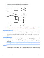
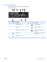
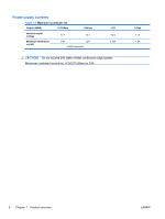
Rear panel components The following figure shows the layout of a typical rear panel. Figure 1-4 Rear panel NOTE: The labels for the rear panel connectors use industry-standard icons and colors. Table 1-3 Rear panel connectors Item Symbol Description Item Symbol Description 1 RJ-45 network connector 6 Display port (DP)1 2 Serial port 7 VGA (monitor)1 3 PS/2 mouse connector (green) 8 PS/2 keyboard connector (purple) 4 Power cord connector 5 USB 2.0 ports (6) 9 Audio line-out connector (green) 10 Audio line-in connector (blue) 1. The DP and VGA ports are disabled if used with Intel® Xeon quad-core processors. 6 Chapter 1 Product overview ENWW
-
 1
1 -
2
-
3
-
4
-
5
-
6
-
7
-
8
-
9
-
10
-
11
-
12
-
 13
13 -
 14
14 -
 15
15 -
 16
16 -
 17
17 -
 18
18 -
 19
19 -
 20
20 -
 21
21 -
 22
22 -
 23
23 -
24
-
25
-
26
-
27
-
28
-
29
-
30
-
31
-
32
-
33
-
34
-
35
-
36
-
37
-
38
-
39
-
40
-
41
-
42
-
43
-
44
-
45
-
46
-
47
-
48
-
49
-
50
-
51
-
52
-
53
-
54
-
55
-
56
-
57
-
58
-
59
-
60
-
61
-
62
-
63
-
64
-
65
-
66
-
67
-
68
-
69
-
70
-
71
-
72
-
73
-
74
-
75
-
76
-
77
-
78
-
79
-
80
-
81
-
82
-
83
-
84
-
85
-
86
-
87
-
88
-
89
-
90
-
91
-
92
-
93
-
94
-
95
-
96
-
97
-
98
-
99
-
100
-
101
-
102
-
103
-
104
-
105
-
106
-
107
-
108
-
109
-
110
-
111
-
112
-
113
-
114
-
115
-
116
-
117
-
118
-
119
-
120
-
121
-
122
-
123
-
124
-
125
-
126
-
127
-
128
-
129
-
130
-
131
-
132
-
133
-
134
-
135
-
136
-
137
-
138
-
139
-
140
-
141
-
142
-
143
-
144
-
145
-
146
-
147
-
148
-
149
-
150
-
151
-
152
-
153
-
154
-
155
-
156
-
157
-
158
-
159
-
160
-
161
-
162
-
163
-
164
-
165
-
166
-
167
-
168
-
169
-
170
-
171
-
172
-
173
-
174
-
175
-
176
-
177
-
178
-
179
-
180
-
181
-
182
-
183
-
184
-
185
-
186
-
187
-
188
-
189
-
190
-
191
-
192
-
193
-
194
-
195
-
196
-
197
-
198
-
199
 |
 |
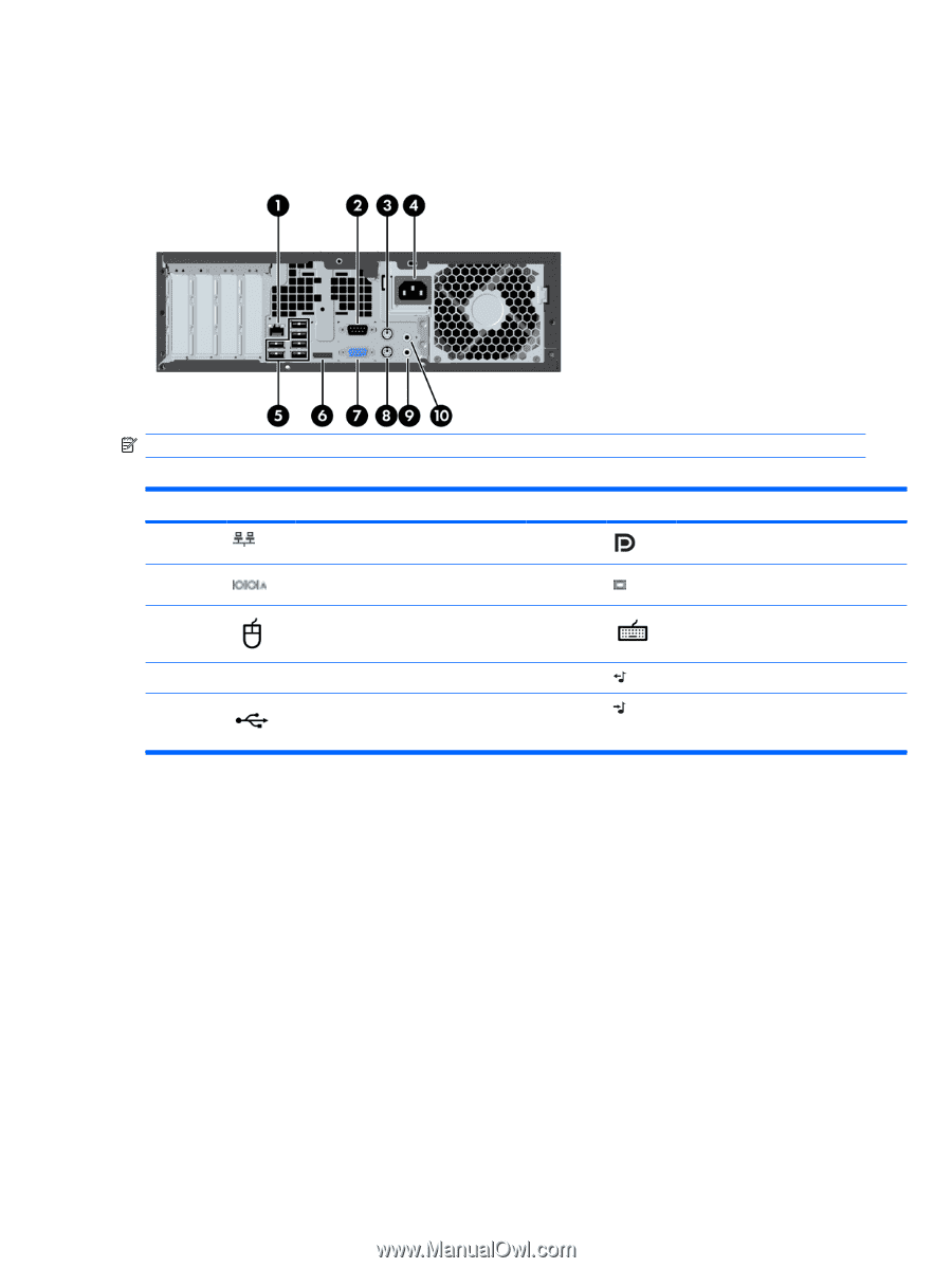
Rear panel components
The following figure shows the layout of a typical rear panel.
Figure 1-4
Rear panel
NOTE:
The labels for the rear panel connectors use industry-standard icons and colors.
Table 1-3
Rear panel connectors
Item
Symbol
Description
Item
Symbol
Description
1
RJ–45 network connector
6
Display port (DP)
1
2
Serial port
7
VGA (monitor)
1
3
PS/2 mouse connector (green)
8
PS/2 keyboard connector (purple)
4
Power cord connector
9
Audio line-out connector (green)
5
USB 2.0 ports (6)
10
Audio line-in connector (blue)
1. The DP and VGA ports are disabled if used with Intel® Xeon quad–core processors.
6
Chapter 1
Product overview
ENWW