HP Z200 HP Z200 SFF Workstation Maintenance and Service Guide - Page 84
Bezel, Removing the front bezel
 |
View all HP Z200 manuals
Add to My Manuals
Save this manual to your list of manuals |
Page 84 highlights
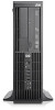
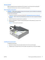
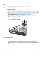
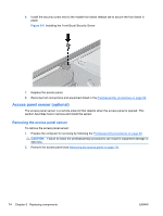
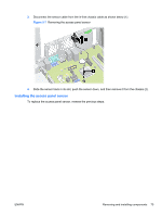
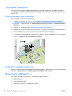
Bezel This section describes how to remove and install the front chassis bezel. Removing the front bezel To remove the front bezel: 1. Prepare the computer for servicing by following the Predisassembly procedures on page 68. CAUTION: Failure to follow the predisassembly procedures can result in equipment damage or data loss. 2. Remove the access panel (see Removing the access panel on page 71). 3. If the security screw is installed (next to the middle front bezel release tab), remove the screw. (See Front bezel security on page 73.) 4. Lift the release tabs (1), and then rotate the front bezel off the chassis (2). Figure 5-4 Removing the front bezel Installing the front bezel To install the front bezel:, align the tabs discussed in the previous section and rotate the bezel until it snaps in place. 1. Align the tabs discussed in the previous section and rotate the bezel until it snaps in place. 2. If you are using the bezel security screw, replace the screw next to the middle front bezel release tab. 72 Chapter 5 Replacing components ENWW
-
 1
1 -
2
-
3
-
4
-
5
-
6
-
7
-
8
-
9
-
10
-
11
-
12
-
13
-
14
-
15
-
16
-
17
-
18
-
19
-
20
-
21
-
22
-
23
-
24
-
25
-
26
-
27
-
28
-
29
-
30
-
31
-
32
-
33
-
34
-
35
-
36
-
37
-
38
-
39
-
40
-
41
-
42
-
43
-
44
-
45
-
46
-
47
-
48
-
49
-
50
-
51
-
52
-
53
-
54
-
55
-
56
-
57
-
58
-
59
-
60
-
61
-
62
-
63
-
64
-
65
-
66
-
67
-
68
-
69
-
70
-
71
-
72
-
73
-
74
-
75
-
76
-
77
-
78
-
 79
79 -
 80
80 -
 81
81 -
 82
82 -
 83
83 -
 84
84 -
 85
85 -
 86
86 -
 87
87 -
 88
88 -
 89
89 -
90
-
91
-
92
-
93
-
94
-
95
-
96
-
97
-
98
-
99
-
100
-
101
-
102
-
103
-
104
-
105
-
106
-
107
-
108
-
109
-
110
-
111
-
112
-
113
-
114
-
115
-
116
-
117
-
118
-
119
-
120
-
121
-
122
-
123
-
124
-
125
-
126
-
127
-
128
-
129
-
130
-
131
-
132
-
133
-
134
-
135
-
136
-
137
-
138
-
139
-
140
-
141
-
142
-
143
-
144
-
145
-
146
-
147
-
148
-
149
-
150
-
151
-
152
-
153
-
154
-
155
-
156
-
157
-
158
-
159
-
160
-
161
-
162
-
163
-
164
-
165
-
166
-
167
-
168
-
169
-
170
-
171
-
172
-
173
-
174
-
175
-
176
-
177
-
178
-
179
-
180
-
181
-
182
-
183
-
184
-
185
-
186
-
187
-
188
-
189
-
190
-
191
-
192
-
193
-
194
-
195
-
196
-
197
-
198
-
199
 |
 |