HP Z200 HP Z200 SFF Workstation Maintenance and Service Guide - Page 81
Disassembly order, Removing the cable lock (optional), If a cable lock is installed on the computer - power supply
 |
View all HP Z200 manuals
Add to My Manuals
Save this manual to your list of manuals |
Page 81 highlights
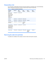
Disassembly order For convenience, disassembly procedures should be followed in a particular order. Use the following table to determine the sequence in which to access major computer components. Table 5-3 computer component installation To install/ replace... Remove... Then remove... Then remove... Then remove... Then remove... Battery, front bezel, optical drive, hard drive, memory, power supply, hood sensor, or solenoid lock Chassis lock Access panel Heatsink Chassis lock Access panel Airflow guide Processor Chassis lock Access panel Airflow guide Heatsink Expansion card (PCI/PCIe) Chassis lock Access panel Expansion card slot cover Front panel I/O assembly, power button assembly, system fan, or system speaker Chassis lock Access panel Front bezel System board Chassis lock Access panel Airflow guide Expansion cards or DIMMs Heatsink Removing the cable lock (optional) If a cable lock is installed on the computer, remove it before servicing the computer. ENWW Removing and installing components 69
-
 1
1 -
2
-
3
-
4
-
5
-
6
-
7
-
8
-
9
-
10
-
11
-
12
-
13
-
14
-
15
-
16
-
17
-
18
-
19
-
20
-
21
-
22
-
23
-
24
-
25
-
26
-
27
-
28
-
29
-
30
-
31
-
32
-
33
-
34
-
35
-
36
-
37
-
38
-
39
-
40
-
41
-
42
-
43
-
44
-
45
-
46
-
47
-
48
-
49
-
50
-
51
-
52
-
53
-
54
-
55
-
56
-
57
-
58
-
59
-
60
-
61
-
62
-
63
-
64
-
65
-
66
-
67
-
68
-
69
-
70
-
71
-
72
-
73
-
74
-
75
-
 76
76 -
 77
77 -
 78
78 -
 79
79 -
 80
80 -
 81
81 -
 82
82 -
 83
83 -
 84
84 -
 85
85 -
 86
86 -
87
-
88
-
89
-
90
-
91
-
92
-
93
-
94
-
95
-
96
-
97
-
98
-
99
-
100
-
101
-
102
-
103
-
104
-
105
-
106
-
107
-
108
-
109
-
110
-
111
-
112
-
113
-
114
-
115
-
116
-
117
-
118
-
119
-
120
-
121
-
122
-
123
-
124
-
125
-
126
-
127
-
128
-
129
-
130
-
131
-
132
-
133
-
134
-
135
-
136
-
137
-
138
-
139
-
140
-
141
-
142
-
143
-
144
-
145
-
146
-
147
-
148
-
149
-
150
-
151
-
152
-
153
-
154
-
155
-
156
-
157
-
158
-
159
-
160
-
161
-
162
-
163
-
164
-
165
-
166
-
167
-
168
-
169
-
170
-
171
-
172
-
173
-
174
-
175
-
176
-
177
-
178
-
179
-
180
-
181
-
182
-
183
-
184
-
185
-
186
-
187
-
188
-
189
-
190
-
191
-
192
-
193
-
194
-
195
-
196
-
197
-
198
-
199
 |
 |