HP Z200 HP Z200 SFF Workstation Maintenance and Service Guide - Page 186
PWRCMD-Power command, P2, CPU power cable, P3, Color, Signal, Internal USB 1 2x5, PSU_DETECT
 |
View all HP Z200 manuals
Add to My Manuals
Save this manual to your list of manuals |
Page 186 highlights
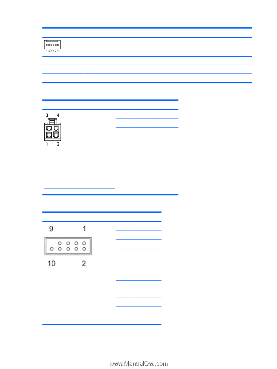
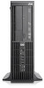
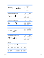
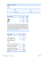
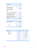
PWRCMD-Power command, P2 4 PWROK 5 GND 6 PSU_DETECT Gray Black (empty) CPU power cable, P3 Pin Color Signal 1 BLK GND 2 BLK GND 3 BRN 12V CPU 4 BRN 12V CPU CAUTION: Never connect the PCIe power cable to the system board when power is on. If you do so, the system board can be damaged and the warranty voided. Ensure that you can tell which power cable connects to the PCIe x16 graphics card and which power cable connects to the system board. These two cables have different pin counts and different colors. The PCIe power cable has a 6-pin black connector, and the CPU power cable has an 4-pin white connector. To see a picture of the PCIe cable and where it must be connected, see Removing and installing expansion cardson page 112. Internal USB 1 2x5 Pin Signal 1 +5V 2 +5V 3 USB6# 4 USB9# CAUTION: Possible equipment damage. 5 The 2x5 connector can be mated to either 6 a wide 2x5 option cable connector or a narrow 1x5 option cable connector. 7 To prevent damage to the connectors, 8 always connect a narrow 1x5 option cable connector to pins 1,3,5, and 7 only of the 9 2x5 connector (pin 9 is not keyed on the connector). 10 USB6 USB9 GND GND (not keyed) DETECT 174 Appendix A Connector pins ENWW
-
 1
1 -
2
-
3
-
4
-
5
-
6
-
7
-
8
-
9
-
10
-
11
-
12
-
13
-
14
-
15
-
16
-
17
-
18
-
19
-
20
-
21
-
22
-
23
-
24
-
25
-
26
-
27
-
28
-
29
-
30
-
31
-
32
-
33
-
34
-
35
-
36
-
37
-
38
-
39
-
40
-
41
-
42
-
43
-
44
-
45
-
46
-
47
-
48
-
49
-
50
-
51
-
52
-
53
-
54
-
55
-
56
-
57
-
58
-
59
-
60
-
61
-
62
-
63
-
64
-
65
-
66
-
67
-
68
-
69
-
70
-
71
-
72
-
73
-
74
-
75
-
76
-
77
-
78
-
79
-
80
-
81
-
82
-
83
-
84
-
85
-
86
-
87
-
88
-
89
-
90
-
91
-
92
-
93
-
94
-
95
-
96
-
97
-
98
-
99
-
100
-
101
-
102
-
103
-
104
-
105
-
106
-
107
-
108
-
109
-
110
-
111
-
112
-
113
-
114
-
115
-
116
-
117
-
118
-
119
-
120
-
121
-
122
-
123
-
124
-
125
-
126
-
127
-
128
-
129
-
130
-
131
-
132
-
133
-
134
-
135
-
136
-
137
-
138
-
139
-
140
-
141
-
142
-
143
-
144
-
145
-
146
-
147
-
148
-
149
-
150
-
151
-
152
-
153
-
154
-
155
-
156
-
157
-
158
-
159
-
160
-
161
-
162
-
163
-
164
-
165
-
166
-
167
-
168
-
169
-
170
-
171
-
172
-
173
-
174
-
175
-
176
-
177
-
178
-
179
-
180
-
 181
181 -
 182
182 -
 183
183 -
 184
184 -
 185
185 -
 186
186 -
 187
187 -
 188
188 -
 189
189 -
 190
190 -
 191
191 -
192
-
193
-
194
-
195
-
196
-
197
-
198
-
199
 |
 |