HP Z200 HP Z200 SFF Workstation Maintenance and Service Guide - Page 110
Installing the front panel I/O device assembly, CAUTION,
 |
View all HP Z200 manuals
Add to My Manuals
Save this manual to your list of manuals |
Page 110 highlights
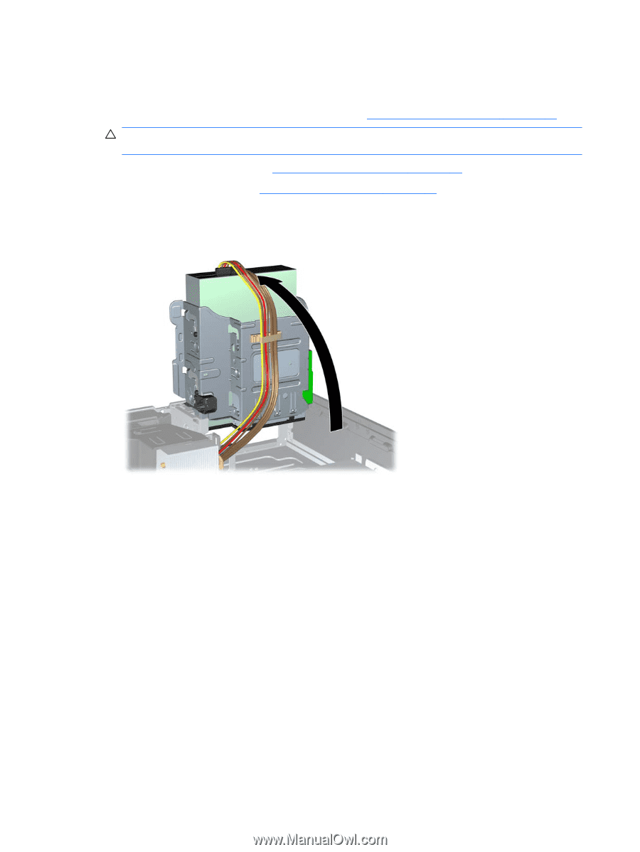
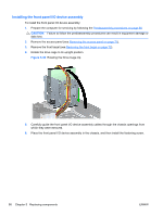
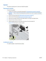
Installing the front panel I/O device assembly To install the front panel I/O device assembly: 1. Prepare the computer for servicing by following the Predisassembly procedures on page 68. CAUTION: Failure to follow the predisassembly procedures can result in equipment damage or data loss. 2. Remove the access panel (see Removing the access panel on page 71). 3. Remove the front bezel (see Removing the front bezel on page 72). 4. Rotate the drive cage to its upright position. Figure 5-36 Rotating the Drive Cage Up 5. Carefully guide the front panel I/O device assembly cables through the chassis openings from which they were removed. 6. Place the front panel I/O device assembly in the chassis, and then install the fastening screw. 98 Chapter 5 Replacing components ENWW
-
 1
1 -
2
-
3
-
4
-
5
-
6
-
7
-
8
-
9
-
10
-
11
-
12
-
13
-
14
-
15
-
16
-
17
-
18
-
19
-
20
-
21
-
22
-
23
-
24
-
25
-
26
-
27
-
28
-
29
-
30
-
31
-
32
-
33
-
34
-
35
-
36
-
37
-
38
-
39
-
40
-
41
-
42
-
43
-
44
-
45
-
46
-
47
-
48
-
49
-
50
-
51
-
52
-
53
-
54
-
55
-
56
-
57
-
58
-
59
-
60
-
61
-
62
-
63
-
64
-
65
-
66
-
67
-
68
-
69
-
70
-
71
-
72
-
73
-
74
-
75
-
76
-
77
-
78
-
79
-
80
-
81
-
82
-
83
-
84
-
85
-
86
-
87
-
88
-
89
-
90
-
91
-
92
-
93
-
94
-
95
-
96
-
97
-
98
-
99
-
100
-
101
-
102
-
103
-
104
-
 105
105 -
 106
106 -
 107
107 -
 108
108 -
 109
109 -
 110
110 -
 111
111 -
 112
112 -
 113
113 -
 114
114 -
 115
115 -
116
-
117
-
118
-
119
-
120
-
121
-
122
-
123
-
124
-
125
-
126
-
127
-
128
-
129
-
130
-
131
-
132
-
133
-
134
-
135
-
136
-
137
-
138
-
139
-
140
-
141
-
142
-
143
-
144
-
145
-
146
-
147
-
148
-
149
-
150
-
151
-
152
-
153
-
154
-
155
-
156
-
157
-
158
-
159
-
160
-
161
-
162
-
163
-
164
-
165
-
166
-
167
-
168
-
169
-
170
-
171
-
172
-
173
-
174
-
175
-
176
-
177
-
178
-
179
-
180
-
181
-
182
-
183
-
184
-
185
-
186
-
187
-
188
-
189
-
190
-
191
-
192
-
193
-
194
-
195
-
196
-
197
-
198
-
199
 |
 |