HP Z200 HP Z200 SFF Workstation Maintenance and Service Guide - Page 106
Power connections, CAUTION,
 |
View all HP Z200 manuals
Add to My Manuals
Save this manual to your list of manuals |
Page 106 highlights
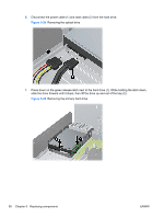
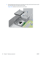
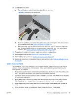
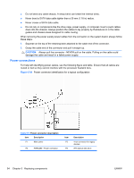
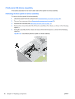
● Do not bend any cable sharply. A sharp bend can break the internal wires. ● Never bend a SATA data cable tighter than a 30 mm (1.18 in) radius. ● Never crease a SATA data cable. ● Do not rely on components like the drive cage, power supply, or computer cover to push cables down into the chassis. Always position the cables to lay properly by themselves or in the cable guides and chassis areas designed for cable routing. When removing the power supply power cables from the connector on the system board, always follow these steps: 1. Squeeze on the top of the retaining latch attached to the cable end of the connector. 2. Grasp the cable end of the connector and pull it straight up. CAUTION: Always pull the connector - NEVER pull on the cable. Pulling on the cable could damage the cable and result in a failed power supply. Power connections For help with identifying power cables, see the following figure and table. Ensure that all cables are routed or tied so they cannot interfere with the processor heatsink fans. Figure 5-31 Power connector identification for a typical configuration Table 5-7 Power connector description Item Description P1 Main power P2 PWRCMD-Power command Item P5 P6 Description 4-pin connector for legacy devices (P9) Optical disk drive 94 Chapter 5 Replacing components ENWW
-
 1
1 -
2
-
3
-
4
-
5
-
6
-
7
-
8
-
9
-
10
-
11
-
12
-
13
-
14
-
15
-
16
-
17
-
18
-
19
-
20
-
21
-
22
-
23
-
24
-
25
-
26
-
27
-
28
-
29
-
30
-
31
-
32
-
33
-
34
-
35
-
36
-
37
-
38
-
39
-
40
-
41
-
42
-
43
-
44
-
45
-
46
-
47
-
48
-
49
-
50
-
51
-
52
-
53
-
54
-
55
-
56
-
57
-
58
-
59
-
60
-
61
-
62
-
63
-
64
-
65
-
66
-
67
-
68
-
69
-
70
-
71
-
72
-
73
-
74
-
75
-
76
-
77
-
78
-
79
-
80
-
81
-
82
-
83
-
84
-
85
-
86
-
87
-
88
-
89
-
90
-
91
-
92
-
93
-
94
-
95
-
96
-
97
-
98
-
99
-
100
-
 101
101 -
 102
102 -
 103
103 -
 104
104 -
 105
105 -
 106
106 -
 107
107 -
 108
108 -
 109
109 -
 110
110 -
 111
111 -
112
-
113
-
114
-
115
-
116
-
117
-
118
-
119
-
120
-
121
-
122
-
123
-
124
-
125
-
126
-
127
-
128
-
129
-
130
-
131
-
132
-
133
-
134
-
135
-
136
-
137
-
138
-
139
-
140
-
141
-
142
-
143
-
144
-
145
-
146
-
147
-
148
-
149
-
150
-
151
-
152
-
153
-
154
-
155
-
156
-
157
-
158
-
159
-
160
-
161
-
162
-
163
-
164
-
165
-
166
-
167
-
168
-
169
-
170
-
171
-
172
-
173
-
174
-
175
-
176
-
177
-
178
-
179
-
180
-
181
-
182
-
183
-
184
-
185
-
186
-
187
-
188
-
189
-
190
-
191
-
192
-
193
-
194
-
195
-
196
-
197
-
198
-
199
 |
 |