HP Z200 HP Z200 SFF Workstation Maintenance and Service Guide - Page 100
Removing and replacing the primary hard drive, CAUTION
 |
View all HP Z200 manuals
Add to My Manuals
Save this manual to your list of manuals |
Page 100 highlights
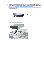
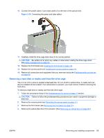
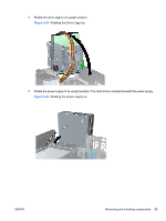
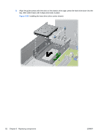
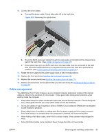
5. Place the drive's guide screws into the J-slots in the drive bay. Then slide the drive toward the front of the computer until it locks into place. TIP: Angle the drive toward one side of the chassis to line up the guide screws with the slots. Figure 5-22 Installing a drive into the drive cage (media card reader shown) 6. Connect the drive cables: a. If installing a second hard drive, connect the power and data cables to the rear of the drive and connect the other end of the data cable to the next available (unpopulated) SATA connector on the system board by following the numbered sequence of the connectors. b. If installing a media card reader, connect the USB cable from the media card reader to the USB connector on the system board labeled MEDIA. If the media card reader includes a 1394 port, connect the 1394 cable to the 1394 PCI card. NOTE: See Locate system board drive connections on page 78 for an illustration of the system board drive connectors. 7. Replace the optical drive. (See Installing an optical drive on page 82.) 8. Replace the front bezel (see Installing the front bezel on page 72). 9. Replace the access panel (see Installing the access panel on page 71). 10. Restore all connections and equipment that you removed during the Predisassembly procedures on page 68. Removing and replacing the primary hard drive The preinstalled 3.5-inch hard drive is located under the power supply. To remove and replace the hard drive: 1. Follow the procedures listed in the Predisassembly for drives on page 77 section. CAUTION: Failure to follow the predisassembly procedures can result in equipment damage or data loss. 2. Remove the access panel (see Removing the access panel on page 71). 3. Remove the front bezel (see Removing the front bezel on page 72). 88 Chapter 5 Replacing components ENWW
-
 1
1 -
2
-
3
-
4
-
5
-
6
-
7
-
8
-
9
-
10
-
11
-
12
-
13
-
14
-
15
-
16
-
17
-
18
-
19
-
20
-
21
-
22
-
23
-
24
-
25
-
26
-
27
-
28
-
29
-
30
-
31
-
32
-
33
-
34
-
35
-
36
-
37
-
38
-
39
-
40
-
41
-
42
-
43
-
44
-
45
-
46
-
47
-
48
-
49
-
50
-
51
-
52
-
53
-
54
-
55
-
56
-
57
-
58
-
59
-
60
-
61
-
62
-
63
-
64
-
65
-
66
-
67
-
68
-
69
-
70
-
71
-
72
-
73
-
74
-
75
-
76
-
77
-
78
-
79
-
80
-
81
-
82
-
83
-
84
-
85
-
86
-
87
-
88
-
89
-
90
-
91
-
92
-
93
-
94
-
 95
95 -
 96
96 -
 97
97 -
 98
98 -
 99
99 -
 100
100 -
 101
101 -
 102
102 -
 103
103 -
 104
104 -
 105
105 -
106
-
107
-
108
-
109
-
110
-
111
-
112
-
113
-
114
-
115
-
116
-
117
-
118
-
119
-
120
-
121
-
122
-
123
-
124
-
125
-
126
-
127
-
128
-
129
-
130
-
131
-
132
-
133
-
134
-
135
-
136
-
137
-
138
-
139
-
140
-
141
-
142
-
143
-
144
-
145
-
146
-
147
-
148
-
149
-
150
-
151
-
152
-
153
-
154
-
155
-
156
-
157
-
158
-
159
-
160
-
161
-
162
-
163
-
164
-
165
-
166
-
167
-
168
-
169
-
170
-
171
-
172
-
173
-
174
-
175
-
176
-
177
-
178
-
179
-
180
-
181
-
182
-
183
-
184
-
185
-
186
-
187
-
188
-
189
-
190
-
191
-
192
-
193
-
194
-
195
-
196
-
197
-
198
-
199
 |
 |