HP Z200 HP Z200 SFF Workstation Maintenance and Service Guide - Page 121
CAUTION, Replace the front bezel see
 |
View all HP Z200 manuals
Add to My Manuals
Save this manual to your list of manuals |
Page 121 highlights
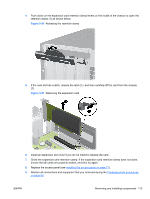
5. Align the DIMM connector key with the DIMM socket key, and then seat the DIMM firmly in the socket (1). CAUTION: DIMMs and their sockets are keyed for proper installation. To prevent socket or DIMM damage, align these guides properly when installing DIMMs. Figure 5-48 Opening DIMM socket levers 6. Secure the socket levers (2). 7. Rotate the drive cage and the power supply down to their normal positions. 8. Replace the front bezel (see Installing the front bezel on page 72). 9. Replace the access panel (see Installing the access panel on page 71). 10. Restore all connections and equipment that you removed during the Predisassembly procedures on page 68. ENWW Removing and installing components 109
-
 1
1 -
2
-
3
-
4
-
5
-
6
-
7
-
8
-
9
-
10
-
11
-
12
-
13
-
14
-
15
-
16
-
17
-
18
-
19
-
20
-
21
-
22
-
23
-
24
-
25
-
26
-
27
-
28
-
29
-
30
-
31
-
32
-
33
-
34
-
35
-
36
-
37
-
38
-
39
-
40
-
41
-
42
-
43
-
44
-
45
-
46
-
47
-
48
-
49
-
50
-
51
-
52
-
53
-
54
-
55
-
56
-
57
-
58
-
59
-
60
-
61
-
62
-
63
-
64
-
65
-
66
-
67
-
68
-
69
-
70
-
71
-
72
-
73
-
74
-
75
-
76
-
77
-
78
-
79
-
80
-
81
-
82
-
83
-
84
-
85
-
86
-
87
-
88
-
89
-
90
-
91
-
92
-
93
-
94
-
95
-
96
-
97
-
98
-
99
-
100
-
101
-
102
-
103
-
104
-
105
-
106
-
107
-
108
-
109
-
110
-
111
-
112
-
113
-
114
-
115
-
 116
116 -
 117
117 -
 118
118 -
 119
119 -
 120
120 -
 121
121 -
 122
122 -
 123
123 -
 124
124 -
 125
125 -
 126
126 -
127
-
128
-
129
-
130
-
131
-
132
-
133
-
134
-
135
-
136
-
137
-
138
-
139
-
140
-
141
-
142
-
143
-
144
-
145
-
146
-
147
-
148
-
149
-
150
-
151
-
152
-
153
-
154
-
155
-
156
-
157
-
158
-
159
-
160
-
161
-
162
-
163
-
164
-
165
-
166
-
167
-
168
-
169
-
170
-
171
-
172
-
173
-
174
-
175
-
176
-
177
-
178
-
179
-
180
-
181
-
182
-
183
-
184
-
185
-
186
-
187
-
188
-
189
-
190
-
191
-
192
-
193
-
194
-
195
-
196
-
197
-
198
-
199
 |
 |
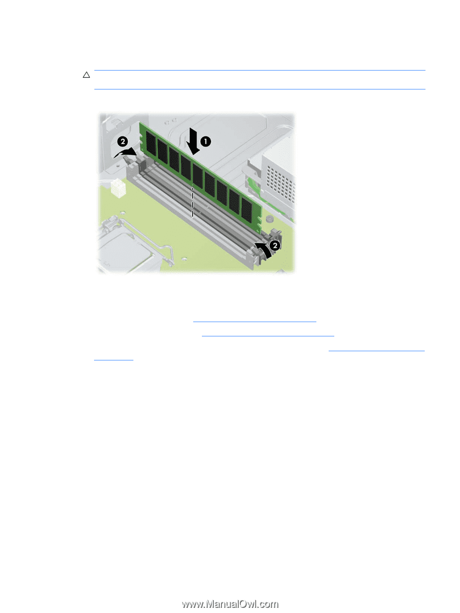
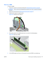
5.
Align the DIMM connector key with the DIMM socket key, and then seat the DIMM firmly in the
socket (1).
CAUTION:
DIMMs and their sockets are keyed for proper installation. To prevent socket or DIMM
damage, align these guides properly when installing DIMMs.
Figure 5-48
Opening DIMM socket levers
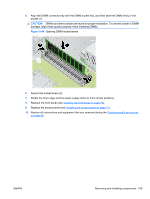
6.
Secure the socket levers (2).
7.
Rotate the drive cage and the power supply down to their normal positions.
8.
Replace the front bezel (see
Installing the front bezel
on page
72
).
9.
Replace the access panel (see
Installing the access panel
on page
71
).
10.
Restore all connections and equipment that you removed during the
Predisassembly procedures
on page
68
.
ENWW
Removing and installing components
109