HP Z200 HP Z200 SFF Workstation Maintenance and Service Guide - Page 122
Expansion card slot identification, Slot identification and description - memory configuration
 |
View all HP Z200 manuals
Add to My Manuals
Save this manual to your list of manuals |
Page 122 highlights
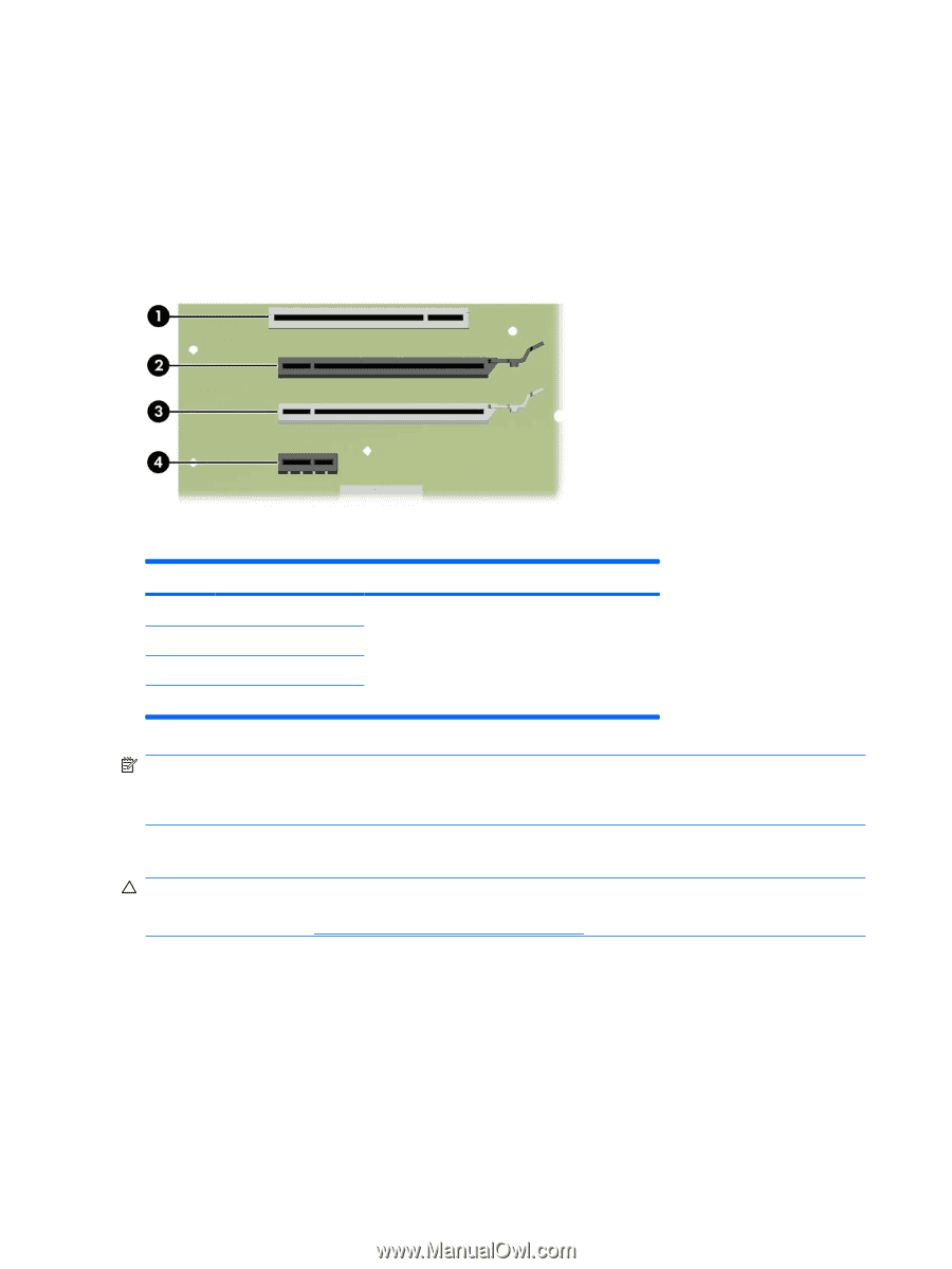
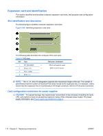
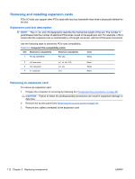
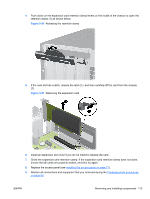
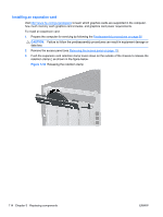
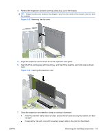
Expansion card slot identification This section identifies and describes computer expansion card slots, and presents card configuration information. Slot identification and description The following figure identifies computer expansion card slots. Figure 5-49 Identifying expansion card slots The following table describes the computer PCIe card slots. Table 5-8 PCI slots Slot Type Slot power (maximum) 1 PCI 32b/33MHZ ● 2 PCIe2 - x16 ● 45W for all graphics cards 80W for all I/O devices 3 PCIe - x16(4) 4 PCIe1 - x1 NOTE: The x1, x4, and x16 designators describe the mechanical length of the slot. The number in parentheses lists the number of electrical PCIe lanes routed to the expansion slot. For example, x16(4) means that the expansion slot is mechanically a x16 length connector, with four PCIe lanes connected. Card configuration restrictions for power supplies CAUTION: To prevent damage, the overall power consumption of the computer (including I/O cards, CPU, and memory) must not exceed the maximum rating of the computer power supply. For power supply information, see Power supply specificationson page 9. 110 Chapter 5 Replacing components ENWW
-
 1
1 -
2
-
3
-
4
-
5
-
6
-
7
-
8
-
9
-
10
-
11
-
12
-
13
-
14
-
15
-
16
-
17
-
18
-
19
-
20
-
21
-
22
-
23
-
24
-
25
-
26
-
27
-
28
-
29
-
30
-
31
-
32
-
33
-
34
-
35
-
36
-
37
-
38
-
39
-
40
-
41
-
42
-
43
-
44
-
45
-
46
-
47
-
48
-
49
-
50
-
51
-
52
-
53
-
54
-
55
-
56
-
57
-
58
-
59
-
60
-
61
-
62
-
63
-
64
-
65
-
66
-
67
-
68
-
69
-
70
-
71
-
72
-
73
-
74
-
75
-
76
-
77
-
78
-
79
-
80
-
81
-
82
-
83
-
84
-
85
-
86
-
87
-
88
-
89
-
90
-
91
-
92
-
93
-
94
-
95
-
96
-
97
-
98
-
99
-
100
-
101
-
102
-
103
-
104
-
105
-
106
-
107
-
108
-
109
-
110
-
111
-
112
-
113
-
114
-
115
-
116
-
 117
117 -
 118
118 -
 119
119 -
 120
120 -
 121
121 -
 122
122 -
 123
123 -
 124
124 -
 125
125 -
 126
126 -
 127
127 -
128
-
129
-
130
-
131
-
132
-
133
-
134
-
135
-
136
-
137
-
138
-
139
-
140
-
141
-
142
-
143
-
144
-
145
-
146
-
147
-
148
-
149
-
150
-
151
-
152
-
153
-
154
-
155
-
156
-
157
-
158
-
159
-
160
-
161
-
162
-
163
-
164
-
165
-
166
-
167
-
168
-
169
-
170
-
171
-
172
-
173
-
174
-
175
-
176
-
177
-
178
-
179
-
180
-
181
-
182
-
183
-
184
-
185
-
186
-
187
-
188
-
189
-
190
-
191
-
192
-
193
-
194
-
195
-
196
-
197
-
198
-
199
 |
 |