HP Z200 HP Z200 SFF Workstation Maintenance and Service Guide - Page 105
Cable management,
 |
View all HP Z200 manuals
Add to My Manuals
Save this manual to your list of manuals |
Page 105 highlights
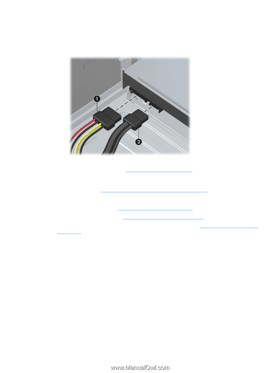
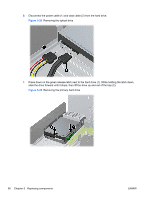
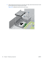
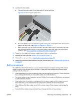
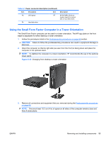
10. Connect the drive cables: a. Connect the power cable (1) and data cable (2) to the hard drive. Figure 5-30 Removing the optical drive b. Route the SATA and power cables through the cable guide on the bottom of the chassis frame behind the hard drive. (See Cable management on page 93.) c. If the system has only one SATA hard drive, the data cable must be connected to the dark blue connector labeled SATA0 on the system board to avoid any hard drive performance problems. (See Locate system board drive connections on page 78.) 11. Rotate the drive cage and the power supply down to their normal positions. 12. Replace the front bezel (see Installing the front bezel on page 72). 13. Replace the access panel (see Installing the access panel on page 71). 14. Restore all connections and equipment that you removed during the Predisassembly procedures on page 68. Cable management The Z200 Small Form Factor chassis is a very compact computer and proper routing of the internal cables is critical to the operation of the computer. Follow good cable management practices when working inside the computer ● Keep cables away from direct contact with major heat sources like the heat sink. (The air flow guide has a cable guide that lets you route cables safely around the heatsink.) ● Do not jam cables on top of expansion cards or DIMMs. Circuit cards and DIMMs are not designed to take excessive pressure. ● Keep cables clear of movable or rotating parts like the power supply and drive cage to prevent them from being cut or crimped when the component is lowered into its normal position ● When folding a flat ribbon cable, never fold to a sharp crease. Sharp creases may damage the wires. ● Some flat ribbon cables come prefolded. Never change the folds on these cables. ENWW Removing and installing components 93
-
 1
1 -
2
-
3
-
4
-
5
-
6
-
7
-
8
-
9
-
10
-
11
-
12
-
13
-
14
-
15
-
16
-
17
-
18
-
19
-
20
-
21
-
22
-
23
-
24
-
25
-
26
-
27
-
28
-
29
-
30
-
31
-
32
-
33
-
34
-
35
-
36
-
37
-
38
-
39
-
40
-
41
-
42
-
43
-
44
-
45
-
46
-
47
-
48
-
49
-
50
-
51
-
52
-
53
-
54
-
55
-
56
-
57
-
58
-
59
-
60
-
61
-
62
-
63
-
64
-
65
-
66
-
67
-
68
-
69
-
70
-
71
-
72
-
73
-
74
-
75
-
76
-
77
-
78
-
79
-
80
-
81
-
82
-
83
-
84
-
85
-
86
-
87
-
88
-
89
-
90
-
91
-
92
-
93
-
94
-
95
-
96
-
97
-
98
-
99
-
 100
100 -
 101
101 -
 102
102 -
 103
103 -
 104
104 -
 105
105 -
 106
106 -
 107
107 -
 108
108 -
 109
109 -
 110
110 -
111
-
112
-
113
-
114
-
115
-
116
-
117
-
118
-
119
-
120
-
121
-
122
-
123
-
124
-
125
-
126
-
127
-
128
-
129
-
130
-
131
-
132
-
133
-
134
-
135
-
136
-
137
-
138
-
139
-
140
-
141
-
142
-
143
-
144
-
145
-
146
-
147
-
148
-
149
-
150
-
151
-
152
-
153
-
154
-
155
-
156
-
157
-
158
-
159
-
160
-
161
-
162
-
163
-
164
-
165
-
166
-
167
-
168
-
169
-
170
-
171
-
172
-
173
-
174
-
175
-
176
-
177
-
178
-
179
-
180
-
181
-
182
-
183
-
184
-
185
-
186
-
187
-
188
-
189
-
190
-
191
-
192
-
193
-
194
-
195
-
196
-
197
-
198
-
199
 |
 |