HP Z200 HP Z200 SFF Workstation Maintenance and Service Guide - Page 124
Removing and installing expansion cards, Expansion card slot description, Removing an expansion card
 |
View all HP Z200 manuals
Add to My Manuals
Save this manual to your list of manuals |
Page 124 highlights
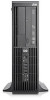
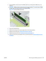
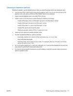
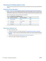
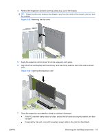
Removing and installing expansion cards PCIe I/O slots can support other PCIe cards with less bus bandwidth than what is physically defined for the slot. Expansion card slot description NOTE: The x1, x4, and x16 designators describe the mechanical length of the slot. The number in parentheses lists the number of electrical PCIe lanes routed to the expansion slot. For example, x16(4) means that the expansion slot is mechanically a x16 length connector, with four PCIe lanes connected. Use the following table to determine PCIe card compatibility. Table 5-9 Computer PCIe compatibility matrix Slot Mechanical compatibility Electrical compatibility 1 PCI 32-bit/33MHz PCI only Color White 2 x16 connector 3 x16 connector 4 x1 connector (x1, x4, x8, x16) (x1, x4) (x1) Black White Black Removing an expansion card To remove an expansion card: 1. Prepare the computer for servicing by following the Predisassembly procedures on page 68. CAUTION: Failure to follow the predisassembly procedures can result in equipment damage or data loss. 2. Remove the access panel (see Removing the access panel on page 71). 3. Remove any cables connected to the expansion card. 112 Chapter 5 Replacing components ENWW
-
 1
1 -
2
-
3
-
4
-
5
-
6
-
7
-
8
-
9
-
10
-
11
-
12
-
13
-
14
-
15
-
16
-
17
-
18
-
19
-
20
-
21
-
22
-
23
-
24
-
25
-
26
-
27
-
28
-
29
-
30
-
31
-
32
-
33
-
34
-
35
-
36
-
37
-
38
-
39
-
40
-
41
-
42
-
43
-
44
-
45
-
46
-
47
-
48
-
49
-
50
-
51
-
52
-
53
-
54
-
55
-
56
-
57
-
58
-
59
-
60
-
61
-
62
-
63
-
64
-
65
-
66
-
67
-
68
-
69
-
70
-
71
-
72
-
73
-
74
-
75
-
76
-
77
-
78
-
79
-
80
-
81
-
82
-
83
-
84
-
85
-
86
-
87
-
88
-
89
-
90
-
91
-
92
-
93
-
94
-
95
-
96
-
97
-
98
-
99
-
100
-
101
-
102
-
103
-
104
-
105
-
106
-
107
-
108
-
109
-
110
-
111
-
112
-
113
-
114
-
115
-
116
-
117
-
118
-
 119
119 -
 120
120 -
 121
121 -
 122
122 -
 123
123 -
 124
124 -
 125
125 -
 126
126 -
 127
127 -
 128
128 -
 129
129 -
130
-
131
-
132
-
133
-
134
-
135
-
136
-
137
-
138
-
139
-
140
-
141
-
142
-
143
-
144
-
145
-
146
-
147
-
148
-
149
-
150
-
151
-
152
-
153
-
154
-
155
-
156
-
157
-
158
-
159
-
160
-
161
-
162
-
163
-
164
-
165
-
166
-
167
-
168
-
169
-
170
-
171
-
172
-
173
-
174
-
175
-
176
-
177
-
178
-
179
-
180
-
181
-
182
-
183
-
184
-
185
-
186
-
187
-
188
-
189
-
190
-
191
-
192
-
193
-
194
-
195
-
196
-
197
-
198
-
199
 |
 |